SilverStone Launches SST-TP01-M.2 Thermal Pads for M.2 SSDs
by Anton Shilov on February 23, 2017 5:00 PM EST- Posted in
- Cases/Cooling/PSUs
- Storage
- SSDs
- SilverStone
- cooling
- M.2
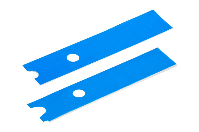
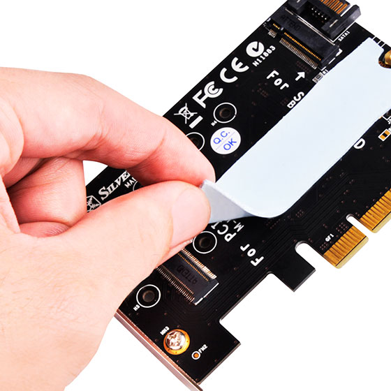
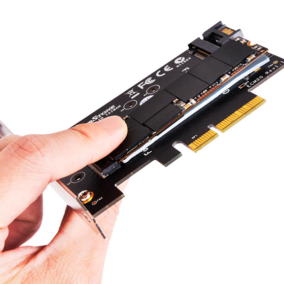
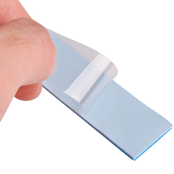
In a bit of offbeat news this afternoon, SilverStone has announced a set of thermal pads for M.2 SSDs, the SST-TP01-M.2. These pads are designed to eliminate (or at least reduce) throttling of modern, high-performance drives under high loads. The pads are made of silicone and Silverstone claims they can reduce temperature of SSDs by over 10°C.
M.2 SSDs have a number of advantages over drives in traditional 2.5” form-factor: they are smaller, they are faster (because they use the PCIe interface with the NVMe protocol), they are (sometimes) cheaper to make, and so on. However, one of the main drawbacks of higher-end M.2 SSDs is the high heat dissipation of their controllers (and memory chips) despite their small form factor, which can lead to thermal throttling and reduced overall performance. Manufacturers have been aware of this for a bit now and have been addressing it in a couple of different ways. Plextor, for example, installs aluminum heat spreaders on their M8Pe drives, whereas Samsung’s latest HDDs come with other types of heat spreaders. However since not all SSD suppliers equip their products with sufficient cooling, SilverStone has developed an aftermarket thermal pad that should work with most drives.
The SilverStone SST-TP01-M.2 thermal pads are made of electrically non-conductive silicone – a material that offers decent thermal conductivity (up to 4 W/m.k) – and can fit M.2 drives that are up to 110 mm long. The SST-TP01-M.2 package includes both 0.5 mm and 1.5 mm thick pads for accommodating different setups.
According to SilverStone, usage of the thermal pads can reduce temperature of Samsung’s SM951 SSDs from 86°C to 71.4°C under high loads, thus ensuring they operate at peak performance more often. The actual performance of SilverSone’s thermal pads will heavily depend on the SSD and the surrounding system – the heat still needs to go somewhere – but there's some potential here as silicone heatpads are by no means a new thing in PC hardware and have proven themselves to be useful.
SilverStone has already started to produce its M.2 thermal pads, and in Japan stores in the famous Akihabara district are already demonstrating them. Unfortunately, pricing has not yet been announced. But M.2 SSD owners who suffer from thermal throttling of M.2 SSDs will want to keep an eye on this.
Source: SilverStone


33 Comments
View All Comments
Michael Bay - Thursday, February 23, 2017 - link
What`s the point of such pad if there is no radiator afterwards?Shadowmaster625 - Thursday, February 23, 2017 - link
Right. What is the point of thermally coupling the SSD to the pcb, which is just soldermask covering a layer of epoxy? You want the pad on the top, and then you want a piece of aluminum on top of that. That's how you cool something. Heck, why not just stick a VRM cooler onto each chip?ddriver - Thursday, February 23, 2017 - link
The goal is to use the PCB as a heat sink. It is dumb, but it will have a tangible effect. I bet those pads will cost a ridiculous amount of money for what they are. Note that those pads are not adhesive, they are just pads.It would cost a few bucks to get a small radiator or even just a piece of aluminum and glue it to the SSD top using them 3m double sided thermally conductive adhesive tapes. And it will work much better too.
III-V - Thursday, February 23, 2017 - link
If it's more thermally conductive than air... well there you go. This looks like it transfers heat to the PCB below, which is chock full of copper, and certainly much cooler.Bullwinkle J Moose - Friday, February 24, 2017 - link
"This looks like it transfers heat to the PCB below, which is chock full of copper, and certainly much cooler."------------------------------------------------------------------------------------------------------------------------
It's too thick
How about taking the dimensions of the pad and cutting a thin copper (or alum) sheet about 2.5 times the width of a single pad and the same length as the pad above
Fold copper sheet down the entire length in the middle and glue a tiny copper or aluminum pipe (heatpipe) aprox 2.8" long (avail at your local hobby/craft store) inside the entire length of the fold to draw heat from the copper foil
you could make short cuts in the copper sheet from the outside edge directly towards the heatpipe in the center fold so the heat could only flow in one direction towards the copper pipe from the chips and NOT flow from chip to chip
Clip the heat sink over the M.2 SSD as if it were a money clip and use that thick insulating pad you bought from Silverstone to insulate the motherboard below your REAL heat sink
Total cost?
About $2
meacupla - Friday, February 24, 2017 - link
Are you sure that's going to fit between the usual places where M.2 SSD sits?By usual places, I mean between PCIe slots and back side of mobo.
And some of these mobos coming with their own M.2 heatsinks end up interfering with popular aftermarket heatsinks
Diji1 - Friday, February 24, 2017 - link
I don't think you understand what a heat pipe is.Bullwinkle J Moose - Friday, February 24, 2017 - link
"I don't think you understand what a heat pipe is."-----------------------------------------------------------------
Fine, lets call it a heat sponge, heat sink or a heat thingy
It draws heat from the metal sheet and radiates that heat across the internal surface area as well as across the external metal sheet
If it doesn't fit in the usual places a M.2 slot goes, then motherboard manufacturers are making it wrong
Start designing motherboards right or stick with SATA
LordOfTheBoired - Tuesday, February 28, 2017 - link
Ummm, heat radiated to the interior won't help. Because it will be reabsorbed by that same interior. It is not remotely the same as a fin stack on a conventional heatsink because a fin stack sees a lot of airflow, while the inside of a long narrow tube will see almost none. Real heat pipes (in addition to being far more complex than an empty tube) are not used to dissipate heat, but to transfer it into the fin stack where it CAN be dissipated.Ninhalem - Friday, February 24, 2017 - link
Alright so this solution that Silverstone has come up with isn't going to work very well. Printed Circuit Board (PCB) has a very low thermal conductivity rate (k) of something like 0.30 W/m-K [Watts per meter-Kelvin]. Putting this silicon pad between the drive and the PCB will result in some heat being transferred from the drive to pad, however, once the heat energy is in the pad, that heat has no where to go. The PCB acts as an insulator. Yes, the PCB does have copper in it, but the majority of the material in PCB is FR-4 glass epoxy (glass fiber).So once the heat is in the pad, normally you would have air blowing over the pad to induce forced external convection with the air. Since, there's not a whole lot of air being moved relatively near this pad, you don't have forced convection, you now have natural convection. The rate of heat transfer between these two different modes of convective heat transfer is quite large. So now, what you have with this pad is closer to retaining the heat than getting rid of the heat.
The solution is to move the pad to the top of the drive instead of between the drive and the PCB, so that the pad has access to more natural and forced convection. The rate of natural convection depends on the surface area that is exposed. If the pad is between these objects, the surface area exposed is just the thin sides, but if placed on top, the surface area is the entire top in addition the thin sides. In addition to placing the pad on top, placing a metal (aluminum/copper) finned block on top of the silicon pad would increase the heat transfer to the surrounding air. Fins increase the available surface area, which then increases the convective heat transfer rate.
Disclaimer: I work with FEA thermal analysis (steady state and transient) in ANSYS every day.