Original Link: https://www.anandtech.com/show/5793/intel-z77-motherboard-review-with-ivy-bridge-asrock-asus-gigabyte-and-msi
Intel Z77 Motherboard Review with Ivy Bridge - ASRock, ASUS, Gigabyte, and MSI
by Ian Cutress on May 7, 2012 7:40 PM EST- Posted in
- MSI
- Gigabyte
- ASRock
- Motherboards
- Asus
- Ivy Bridge
- Z77
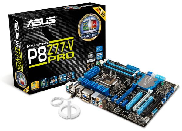
So we have survived one of the biggest days of the year for all things computer performance related - the release of Intel's new Ivy Bridge processor. It replaces Sandy Bridge in the landscape of all things processor related, with Ivy Bridge boasting better single threaded performance at lower power usage when at stock speeds. Despite Ivy Bridge being in the same socket as Sandy Bridge, we have a new trio of chipsets to tackle. As in my previous chipset and motherboard preview, AnandTech has a series of boards ready to put through their paces with the glory of Ivy Bridge. Today we begin with the first set of boards - the ASRock Z77 Extreme4, the ASUS P8Z77-V Pro, the Gigabyte GA-Z77X-UD3H, and the MSI Z77A-GD65.
ASRock Z77 Extreme4 - Overview
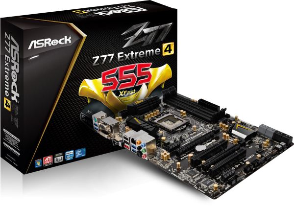
In the early reviews of a new chipset, and a new processor, there is often a delay between initial testing and understanding a platform. In this circumstance, ASRock have the dubious honor of being my first victim for Ivy Bridge. Typically the lower end Extreme models from ASRock have solid performance, are priced extremely competitively and come with many extras. In this case, the Z77 Extreme4 board currently retails for $140, but does not come with a lot more than the board itself.
From the results, we notice that ASRock is perhaps a little behind. However, this is more indicative of a larger issue regarding certain options that motherboard manufacturers are implementing to appear to be better in multithreaded scenarios. It boils down to how each manufacturer implements turbo modes. So there is a big chance we will see these ‘tweaks’ being implemented on future BIOSes across all the motherboard manufacturers, including ASRock.
The BIOS and software are ASRock standard, with XFast USB providing faster speeds for an individual USB port, XFast LAN allowing configuration of the network controller, and XFast USB giving RAMDisk options for large memory configurations. The software is spread across several programs, which perhaps in the future will be integrated into one interface. I do like the Internet Flash feature in the BIOS though, which downloads the latest BIOS and applies it without ever needing an operating system (as long as the motherboard is connected to the internet via Ethernet).
One 'issue' I had (which I have experienced on the past few ASRock boards I have tested) was that by default the CPU fan speed is set at 100% to minimize temperatures on the CPU. The downside of this is increased noise, so users should be aware and adjust accordingly. The fan controls themselves are not very sophisticated compared to other manufacturers, so I hope these will evolve over time.
Overall, the board is very easy to use, but the package as a whole which backs ASRock’s products has room to grow.
Visual Inspection
ASRock is still insistent with bringing the black gold philosophy to its range, as seen here with the Z77 Extreme4. The main point you may immediately notice is the size and depth of the heatsinks covering up the power delivery - they are smaller than previous iterations of ASRock boards, and no longer connected via a heatpipe. This is indicative of quite a few boards in the Z77 range, due to the low power requirements of the new processors and as a result, the lack of heat given away.
The socket area is relatively clean, especially to the south where we have no large intruding heatsink. The VRM heatsinks however do brush right up against the Intel specifications for the socket area, so users ultimately have only two directions (to the PCIe and towards the memory) in which to play around with big air coolers. The socket area is adorned with five fan headers - three along the top edge of the board and two chassis headers near the top PCIe x1 slot. The other header on board is along the bottom next to the two-digit debug.
The board is actually not a full ATX sized board - from left to right, it measures only 21.8 cm, rather than the standard ATX size of 24.4 cm. As a result, this means ASRock do not have to deal with the far right holes in the motherboard for case mounting, and hence why the SATA ports in the bottom right are neatly tucked away. In this corner, we have the six SATA ports from the PCH (two SATA 6 Gbps, four SATA 3 Gbps) and another two from an ASMedia ASM1061 controller (SATA3_A1 is shared with an eSATA port, however). The internal USB 3.0 header is located nearer the 24-pin ATX power connector, perhaps indicating that is for both front case use and rear case use, taking up the space where the first PCIe x1 is.
The chipset heatsink is rather small, compared to Z68 and X79 boards, and is not connected via heatpipe to any other heatsink nearby. On the south side of the board are the standard array of audio and USB headers, along with a fan header and power/reset buttons. It is good also to see the two-digit debug on the board as well.
The PCIe layout is indicative of what we will see on many Z77 boards this year, which do not use any form of PCIe lane expansion, such as a PLX chip. In this case, we have an x1, an x16 (x8 on a dual card setup), a gap, a PCI, an x8, another PCI, and another x1. This is some smart thinking, as even with a dual GPU setup there is space for two single width PCIe x1 cards and a PCI card (which contrary to what some people think are still used in reasonable numbers).

Despite the stock image from ASRock looking a little bent on the back panel, we have a typical Z77 arrangement for IO. From left to right, a combination PS/2 port, two USB 3.0 ports (blue), a D-Sub output, a DVI-D output, HDMI, a clear CMOS button, two USB 2.0 ports (black), an eSATA port (red), gigabit Ethernet, two more USB 3.0 ports (blue), and a standard array of audio jacks featuring an optical SPDIF output.
Board Features
| ASRock Z77 Extreme4 | |
| Price | Link |
| Size | ATX |
| CPU Interface | LGA-1155 |
| Chipset | Intel Z77 |
| Power Delivery | 8 + 4 Phase |
| Memory Slots |
Four DDR3 DIMM slots supporting up to 32 GB Up to Dual Channel, 1066-2800 MHz |
| Video Outputs | HDMI 1.4a, DVI-D, D-Sub |
| Onboard LAN | Broadcom BCM57781 |
| Onboard Audio | Realtek ALC898 |
| Expansion Slots |
2 x PCIe x16 Gen3 2 x PCIe x1 Gen2 2 x PCI |
| Onboard SATA/RAID |
2 x SATA 6 Gbps (PCH), Support for RAID 0, 1, 5, 10 2 x SATA 6 Gbps (ASMedia ASM1061) 4 x SATA 3 Gbps (PCH), Support for RAID 0, 1, 5, 10 |
| USB |
Two USB 3.0 at rear (PCH) Two USB 3.0 at rear (ASMedia 1042) One USB 3.0 header (PCH) |
| Onboard |
4 x SATA 6 Gbps 4 x SATA 3 Gbps 1 x IR Header 1 x CIR Header 1 x COM Header 1 x SPDIF Header Power/Reset Buttons Two Digit Debug LED 6 x Fan Headers Front panel audio connector 3 x USB 2.0 headers (support 6 USB 2.0 ports) 1 x USB 3.0 header (supports 2 USB 3.0 ports) |
| Power Connectors |
1 x 24-pin ATX connector 1 x 8-pin 12V connector |
| Fan Headers |
2 x CPU Fan Header (one 4-pin, one 3-pin) 3 x CHA Fan Headers (one 4-pin, two 3-pin) 1 x PWR Fan Headers (3-pin) |
| IO Panel |
1 x Combo PS/2 Port 1 x HDMI 1.4a 1 x DVI-D 1 x D-Sub 1 x Optical SPDIF 2 x USB 2.0 4 x USB 3.0 1 x eSATA 6 Gbps 1 x Gigabit Ethernet 1 x Clear CMOS Audio Outputs |
| Warranty Period | 3 years from date of purchase |
| Product Page | Link |
Rather than dump a Realtek NIC/Audio combination on this board, ASRock has gone for a Broadcom NIC. This means either they have struck a deal with Broadcom, or it works a lot better for their ASRock LAN software. ASRock is the only motherboard manufacturer to state they support HDMI 1.4a on their website specifications as well. As one of the cheaper boards of this roundup, the Z77 Extreme4 actually comes away pretty well in terms of features.
ASRock Z77 Extreme4 – BIOS
The ASRock graphical BIOS has evolved from the initial days of Sandy Bridge into a bright blue screen with options we see below. With a graphical BIOS, there are two things to focus on – presentation and usability. Not by any great stretch of the imagination, one could design a great BIOS for everyone to use – with an infinite color palette and tools it could look amazing. However implementing such a system could be tricky, as a BIOS is currently limited to approximately eight megabytes in size. This has to contain all the initialization parameters for the board, as well as all the BIOS options we get to play with. I can imagine that should that limit ever increase to 16 or 64 MB, we would have a lot nicer things to look at.
I could wax lyrical about what I want in a BIOS, but as it currently stands, we will never get a work of art or functional awesomeness. ASRock make a fair attempt, one of the better ones in fact, and it turns out to be easy to use.
The main screen shows the BIOS version, CPU, memory and frequencies. What would put the cherry on the top would be the CPU voltage and temperatures as well. If there is room, perhaps some fan speeds (similar to ASUS’ EZ mode) should also be included. The main screen also has a system browser element, which is a top down view of the board with details on what is plugged in.
Overclocking options are essentially all bunched in one list in the OC Tweaker menu:
Important options like the CPU multiplier and BCLK are plain to see, as well as voltages and load line calibrations. The ASRock BIOS had no issues in applying the XMP settings on my G.Skill DDR2-2400 kit of memory.
The Internet Flash utility is something new to consumer level BIOSes – ASRock implements this in their Advanced Menu. If your motherboard is linked via Ethernet to the internet (thus on a network, or via ICS), then it will probe the ASRock servers for the latest BIOS. It will then be downloaded and applied without hassle. I really like this feature – it makes my life a lot easier at least!
Fan settings are all controlled in the H/W Monitor screen. This shows temperatures, voltages and fan speeds, and gives options for the various fan headers on-board. The main issue I have with ASRock fan options is the fact that they are not clear. We should have all our options regarding temperatures and target temperatures – instead we get a ‘Level’ system. This means that ASRock should probably invest in better fan controllers so they can talk back to the system regarding RPM, temperatures and relating these all to sensors on-board.
Software
ASRock’s software has not changed in any major detail since their last outing on X79. At the heart of the system is ASRock eXtreme Tuning Utility (AXTU), which controls OS overclocking, fan controls, energy saving and XFast RAM. XFast RAM itself allows 32-bit OS users to unlock memory not found, or 64-bit users to enable a RAMDisk to speed up certain caching utilities in the operating system.
Also from ASRock is the XFast LAN software, which in fact is a licensed version of cFosSpeed with ASRock decals. This software allows full management of the network facilities on the motherboard – shaping traffic for different functions as well as monitoring tools amongst others.
XFast USB is another of ASRock’s licensed software bundled with each motherboard. This utility will change the driver from the standard Windows one to one that can implement BOT (Bulk-Only Transfer) protocols. In reality, this allows for quicker transfers due to less overhead, at the expense of latency. For bulk transfers, I find that this utility works really well, especially with incompressible transfers. The downside being that it is only applied to one USB port at a time.

ASRock Z77 Extreme4 - In The Box
Driver CD
User Manual
IO Shield
2 locking SATA cables
3-slot SLI bridge
Uncharacteristically from ASRock, we do not have a lot to shout about regarding the contents of the box. Previously with the P67 products we had a USB 3.0 bracket, but this time we are limited to just a pair of SATA cables. This is unfortunate, but perhaps was required to hit a price point.
Voltage Readings
Using OCCT we monitor the voltage change of the motherboard under load. This represents the direct correlation between the Load Line Calibration and how the processor/motherboard deals with voltage requests while under load. This is not to be confused with the quality of power delivery, but more an indication of how aggressive the default LLC settings are on a motherboard.
The CPU voltage at load for the ASRock board seems to vary more than the other boards in this review, which may be a result of the price difference. Nevertheless, this is not a series of massive jumps to be concerned over.
Overclocking
Note: Ivy Bridge does not overclock like Sandy Bridge. For a detailed report on the effect of voltage on Ivy Bridge (and thus temperatures and power draw), please read Undervolting and Overclocking on Ivy Bridge.
As the first explanation of overclocking results on a platform, I would highly suggest you read my article on overclocking performance on Ivy Bridge. As the successor to Sandy Bridge, people may expect similar to Sandy Bridge. However, there are a number of key differences, especially in terms of heat generation and applied voltages.
Auto Overclocking: ASRock comes with several automatic overclocking features, however these are all in the BIOS – ‘Enhanced Turbo 30’ and ‘Optimized CPU Setting’. Enhanced Turbo 30 initially calls upon preloaded settings – 4.7 GHz on the CPU, 1600 MHz on the iGPU, +0.085 volt offset on the CPU and CPU load line calibration (LLC) set at ‘Level 1’. This setting did not do anything to the memory, and made the machine run rather hot – 92ºC during OCCT causing it to stop, and 97ºC during PovRay. Both of these temperatures were on the test bed outside a case, so I would not recommend them inside a case!
The Optimized CPU Settings offers CPU speeds in 200 MHz increments. When selected, it adjusts the CPU multiplier but leaves all else on automatic.
- At the 4.4 GHz setting, this gave 1.112 volts on load, 72ºC during PovRay and 70ºC for Blender.
- At the 4.6 GHz setting, this gave 1.192 volts on load, 85ºC during PovRay and 86ºC for OCCT.
- At the 4.8 GHz setting, this gave 1.240 volts constant at LLC Level 1. This caused the blue screen of death on boot.
Manual Overclocking: Given the overview of overclocking on Ivy Bridge, choosing your maximum voltage to aim for a speed is critical. The best combination I achieved on the ASRock Z77 Extreme4 was 4.7 GHz at 1.175 volts, using LLC Level 1. This gave 86ºC during both PovRay and OCCT, which is essentially near the limit as to what I would suggest on Ivy Bridge.
ASUS P8Z77-V Pro – Overview
ASUS has a lot to live up to with its Ivy Bridge Pro board. Both the ASUS P8P67 Pro and ASUS P8Z68-V Pro have been top class sellers in their respective chipsets meaning that ASUS has to deliver. By just looking at the board, it seems that ASUS is keen to innovate and offer a complete package.
In terms of features, by default ASUS has a setting to give a ‘MultiCore Enhancement’. In the real world, this means that by default ASUS will overclock your processor to its maximum turbo mode no matter what the CPU load. For comparison with the 3770K, the CPU should be at 39x during single and dual core mode, 38x when using three cores, and 37x under full load. Using MultiCore Enhancement, you get 39x on all cores no matter what the load. Therefore, in our multithreaded benchmark suite, ASUS has a 200 MHz advantage per core over other products that do not enable this feature by default.
This is obviously on top of the large assortment of features ASUS already provides. The AI Suite software is bolstered by a revised version of Fan Xpert, which can test each fan individually for RPM and allows greater fan configuration. USB 3.0 Boost implements the USB-attached SCSI Protocol on USB 3.0 ports (both Intel [in Windows 8] and ASMedia) to allow greater read-write speeds, especially under high queue depths (if that happens to be your usage scenario). ASUS also plan for the future in giving a Thunderbolt header for use with their Thunderbolt add-in card due for a separate release soon.
I found one issue with the design of the board, relating to CPU coolers. The cooler I use for these reviews is the Intel All-In-One liquid cooler, which uses a standard backplate for multiple sockets. However, with the ASUS Pro, there were placement issues of this backplate due to onboard components:
In order to get the backplate on, I had to bend this pin. This is generally not advised, but it is a shame that this was not caught when the board was designed. It seems that perhaps this board should be paired best with a pushpin cooler to avoid this issue, or something a little newer than my solution. On a more positive note, the board comes with a WiFi module and antennae, which bolt in to the IO panel, and uses an Intel network controller. For audio outputs, we have the full spread of analog and digital that Ivy Bridge can provide.
Visual Inspection
The ASUS P8Z77-V Pro sports a blue and black livery synonymous with their channel / non-ROG products. The VRM heatsinks cover a lot of surface area in their jagged fashion, and around the socket itself, we have access to five main fan headers. Two of these are CPU 4-pin headers just north of the top VRM heatsink, one 4-pin below the left hand side VRM heatsink, and two 4-pin headers below the 24-pin ATX power connector, along with a USB 3.0 port. A sixth fan header (4-pin) is found on the south side of the board. All the fan headers are controllable from the BIOS and in the OS, plus the chassis headers offer 3-pin support.
Above the 24-pin ATX power connector, we find the ASUS MemOK! button, which allows memory recovery to default speeds. Along with the ASRock boards, we have eight SATA ports – four SATA 3 Gbps from the PCH and four SATA 6 Gbps – two from the PCH and two more from an ASMedia controller. Below this are the TPU and EPU switches, designed for enhanced CPU performance and energy saving modes respectively.
Along the bottom of the board is the standard array of a front panel audio header, another USB 3.0 header, USB 2.0 headers, and a front panel header. It is also worth noting the Thunderbolt header on the bottom right of the board for that add-in card, and the BIOS Flashback button which allows a user to flash a new BIOS without memory, CPU or VGA required. In terms of PCIe layout, despite there being three full-length PCIe connectors on board, we are only limited to using two for multi-GPU setups. In order, we have a PCIe x1, a PCIe 3.0 x16 (x8 in dual GPU), x1, PCI, PCIe 3.0 x8, PCI, and a PCIe 2.0 x4. Thus in dual GPU mode we can also add in a PCIe x1 and PCIe x4 card.
The chipset heatsink is indicative of the large but low philosophy of many motherboard manufacturers, hiding away the chipset controller. What is not on these boards, as you may notice, is a combination power/reset pair of buttons, nor a two-digit debug, some of which we used to see on ASUS Pro boards of old. However, ASUS do have Q-LED, a series of lights on board to show when different stages in the POST process are being initialised - useful for diagnosing POST errors.
On the back panel, we have a combination PS/2 port, two USB 3.0 ports (blue), two USB 2.0 ports (black), an ASUS WiFi GO! Card, optical SPDIF output, HDMI, DisplayPort, D-Sub, DVI-D, gigabit Ethernet, two more USB 3.0 ports in blue, and standard audio headers.
This means that rather than add in a WiFi module on the board, or use up a mini-PCIe slot with wifi, we have a slot in order to add a WiFi module. This can be in 2.4 GHz or 5 GHz mode, and updateable as WiFi standards change. This all comes as part of the package, with magnetic wireless antenna to attach to the case.
Board Features
| ASUS P8Z77-V Pro | |
| Price | Link |
| Size | ATX |
| CPU Interface | LGA-1155 |
| Chipset | Intel Z77 |
| Power Delivery | 12 + 4 |
| Memory Slots |
Four DDR3 DIMM slots supporting up to 32 GB Up to Dual Channel |
| Video Outputs | DisplayPort, HDMI 1.4a, DVI-D, D-Sub |
| Onboard LAN | Intel 82579V |
| Onboard Audio | Realtek ALC892 (with DTS Ultra II PC / DTS Connect support) |
| Expansion Slots |
2 x PCIe x16 Gen3 (x16, x8/8) 1 x PCIe x16 Gen2 (x4) 2 x PCIe x1 Gen2 2 x PCI |
| Onboard SATA/RAID |
2 x SATA 6 Gbps (PCH), Support for RAID 0, 1, 5, 10 2 x SATA 6 Gbps (ASMedia) 4 x SATA 3 Gbps (PCH), Support for RAID 0, 1, 5, 10 |
| USB |
Four USB 3.0 at rear (2 PCH, 2 ASMedia) Two USB 3.0 headers on board (PCH, ASMedia) Ten USB 2.0 (2 back panel, 8 on board) |
| Onboard |
4 x SATA 6 Gbps 4 x SATA 3 Gbps 2 x USB 3.0 Headers 4 x USB 2.0 Headers 6 x Fan Headers 1 x SPDIF Header 1 x Front Panel Audio Header Thunderbolt Header MemOK! Button TPU/EPU Switches USB Flashback Button |
| Power Connectors |
1 x 24-pin ATX connector 1 x 8-pin 12V connector |
| Fan Headers |
1 x CPU Fan Header (4-pin) 4 x CHA Fan Headers 1 x OPT Fan Header |
| IO Panel |
1 x PS/2 Combo Port 1 x DisplayPort 1 x HDMI 1.4a 1 x DVI-D 1 x D-Sub 1 x Gigabit Ethernet 4 x USB 3.0 2 x USB 2.0 1 x Optical SPDIF 1 x WLAN Connector 6 x Audio Jacks |
| Warranty Period | 3 Years |
| Product Page | Link |
ASUS is now placing Intel NICs on all their channel motherboards. This is a result of a significant number of their user base requesting them over the Realtek solutions. Also to note are a total of six USB 3.0 on board, two on the back panel and four from internal headers. These USB 3.0 ports can take advantage of the improved UASP USB 3.0 protocol using appropriate hardware and some ASUS software. As always, we expect ASUS fan control of the six headers to be top notch. ASUS also include a TB Header for their add-in Thunderbolt card expected for release soon.
ASUS P8Z77-V Pro – BIOS
ASUS BIOSes, ever since we went graphical back in P67, have been at the top of presentation and usability of the graphical interface. Therefore, it would have been odd if ASUS had done something vastly different for Z77. Luckily, the same interface greets us – initial entry into the BIOS greets us in EZ mode (I still call it ee-zed, being a Brit), which displays the time, the motherboard, the BIOS version, the CPU, the CPU speed, the memory, temperatures, voltages, fan speeds and the boot order. As an entry screen it is very informative, suitable for most users to implement a power saving or turbo mode, or the boot order.
However, the meat of the BIOS is all in the Advanced mode, where the BIOS takes a more traditional look. Screens of interest here are the AI Tweaker, where overclocks are made. This screens below shows an applied Extreme Memory Profile, with MultiCore Enhancement enabled, memory set at the correct strap and additional voltage applied to the memory as defined in the XMP.
Adjusting memory subtimings occurs in the DRAM Timing Control, and DIGI+ Power Control allows adjustment of load line calibrations as well as current capacities should a user desire extreme overclocks. The CPU, VRM, iGPU and DRAM can all benefit from DIGI+ control
ASUS have had good fan profile options in their software, so the options in the BIOS are a little sparse in comparison to their OS offerings, though this could be down to BIOS limitations. Temperatures and fan settings are found in the Monitor section.
Software
ASUS’ AI Suite software is the stalwart of the operating system options, and over the chipset generations I have grown accustomed to it. ASUS is continually updating features in the software, both in relation to hardware changes but also to ideas and requirements of the users. Having all the software under one heading helps with organization and consistency. Now that it is also a few generations old, it no longer has the annoying delay in loading associated with previous versions.
TurboV Evo is the overclocking function of AI Suite. As in previous versions, there is an automatic overclock function (available in ‘Fast’ and ‘Extreme’ modes) as well as a set of manual options. Personally, I use this part of the software to test overclocks, and then apply them in the BIOS later. Therefore, if an overclock is unstable, it does not cause the system to not boot next time around.
ASUS has adjusted the software relating to DIGI+ in order have a more concerted effort to teaching users about it. Alongside the CPU DIGI+ and VRM DIGI+ options, we have a ‘Smart DIGI’ option that can enable the user to use low power DIGI+ settings, or a set of useful settings for overclockers.
Fan Xpert 2 is an upgraded take on the fan software previously distributed with ASUS products. In this instance, when Fan Xpert is loaded, it asks to be able to test all the fans across their full range of speeds. This allows the software to produce graphs relating applied power with actual RPM and performance. So for example, my CPU fan has a minimum of 846 RPM at 23% applied power, up to 2261 RPM at 100%. Below 23% power invokes the minimum RPM setting:
WiFi Go settings also get an upgrade – with the included WiFi module on board a user can set up a multimedia streaming center with the ASUS board in order to send files across to WiFi enabled televisions, or be controlled by tablets with the appropriate apps. File transfer is also available in a similar fashion. The software also allows the PC to act as a wireless access point for the internet.
Alongside the quick charging features (Ai Charger+, USB Charger+) which promise to decrease charge time for smartphones, tablets and Apple products, due to the use of Intel network controllers on board, we have software in order to be able to manipulate network traffic. At its simplest level, this means giving priority to certain applications (games) over others (file transfer):
Other smaller features with AI Suite include the BIOS Flashback utility and software to change the initial boot up logo screen. I purposefully saved talking about USB 3.0 Boost until last, as we now have the ability to test it.
ASUS kindly provided a SATA 3.0 to USB 3.0 hub, along with a high speed SSD to test how their USB 3.0 Boost system in terms of what benefits in can bring over normal USB 3.0. At the heart of the system is the ability to adjust the USB protocol, from the normal Windows protocol, to either a turbo mode (on the chipset USB 3.0) or a USB-attached SCSI protocol (UASP) with a capable device on an ASMedia USB 3.0, or on the Chipset boards with Windows 8.
Both the Turbo and UASP modes offer a different set of commands to the USB in order to improve transfer rates. Initially, I performed my standard CrystalDiskMark test, which uses incompressible data for stress the reads and writes of each of the modes (Intel USB 3.0 Normal, Intel USB 3.0 Turbo, ASMedia USB 3.0 Normal, ASMedia USB 3.0 UASP), followed by our standard USB copy test.
The results ended up with the Intel Turbo mode (which depends on memory speed) outperforming the ASMedia UASP, which seems counter-intuitive. The benefits of UASP are actually outside my own normal usage model for USB – I typically use USB as file storage or as a method of transferring files between systems. The benefits of UASP lie in using a USB device as if it was a drive in the system – in situations where queue depth could be high. With this in mind, I tested all four different USB 3.0 models with ATTO Disk Benchmark and a full suite of CrystalDiskMark:
Alternatively, to put it in a more readable format:
In terms of read speeds at a QD of four, UASP achieves supreme performance when dealing with small (< 64 KB) transfer sizes.
For write speeds, UASP outperforms Turbo across the whole range of Transfer Sizes, again most notably at sub-64 KB transfer sizes.
What we can see is that the add-in controller (ASMedia) with UASP can easily out perform the Intel controller in Normal mode. When the Intel controller is kicked into Turbo mode, it has a direct link to the PCH whereas the ASMedia goes via an x1 PCI-E link. This means under Turbo, the Intel has the advantage at peak loads, but the UASP protocol still wins out under short file transfers due to the efficiency at the command level.
ASUS P8Z77-V Pro - In The Box
The ASUS P8Z77-V Pro retails at $225-$235, essentially $100 more than the ASRock Z77 Extreme4, so I would expect a good amount in the box to help sweeten the price point. Thankfully, we get a good amount!
Driver CD
User Manual
IO Panel
4 SATA Cables
SLI Finger
WiFi Go! 802.11 a/b/g/n WiFi card
WiFi magnetic antenna
USB and eSATA back panel
ASUS Q-Connectors
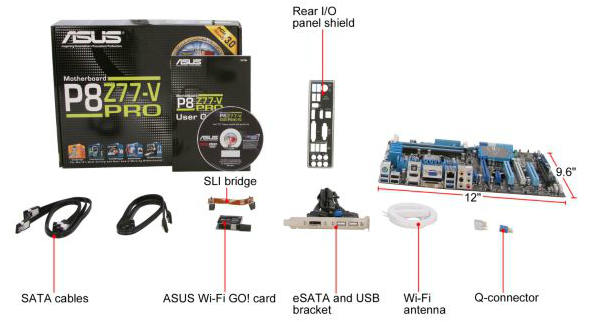
The addition of WiFi on the board obviously adds substantial value – personally, at home, I have my machines connected via WiFi, and ASUS say that at least 25% of their user base is in a similar position, hence the addition to the package.
Voltage Readings
Using OCCT we monitor the voltage change of the motherboard under load. This represents the direct correlation between the Load Line Calibration and how the processor/motherboard deals with voltage requests while under load. This is not to be confused with the quality of power delivery, but more an indication of how aggressive the default LLC settings are on a motherboard.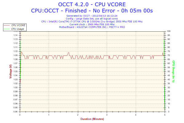
The ASUS board has regular power delivery, with minimal voltage ripple under load.
Overclocking
Note: Ivy Bridge does not overclock like Sandy Bridge. For a detailed report on the effect of voltage on Ivy Bridge (and thus temperatures and power draw), please read Undervolting and Overclocking on Ivy Bridge.
ASUS overclocking tools have been consistent over the few previous chipsets. In the BIOS, OC Tuner is a simple setting that enables a ‘Fast’ overclock on the system. Similarly, the TPU button on board does a similar action. In the OS, the TurboV Evo part of the software offers ‘Fast’ and ‘Extreme’ auto overclocking modes. For manual overclocking, the TurboV Evo software allows the user to play with an overclock in the OS, which should aid in setting a more permanent overclock in the BIOS.
Auto Overclock: ‘Fast’ mode (either through BIOS or OS) implements an immediate 19% overclock, with 41x on the multiplier and 102 MHz base frequency, ending with 4182 MHz overall. This is coupled with a memory overclock, which in my case it did XMP but backed off one memory strap. What was odd was that the memory was set to a 3T command rate!
‘Extreme’ mode implements a algorithmic testing tool in the OS to probe overclock limits. By slowly upping the multiplier and voltage, the system performs stability tests until the system crashes. The system reboots and then implements BCLK tuning, while still monitoring temperatures. In our test, the initial boot implemented a 20% overclock at 41x103 (4223 MHz), and then performed multiplier testing. At 47x, the system restarted to 46x and started BCLK tuning. At 104.5 MHz, the system restarted again, do a ‘Failed Overclock’ screen on boot. After pressing F1 for Setup, then F10 for Save and Exit, the operating system showed an overall 36% overclock – 46x103.8 (4774 MHz). At load, this gave 1.280 volts at load, giving an immense 94ºC peak temperature during PovRay. I do not think I would be happy with that temperature for a daily system.
Manual Overclock: With the overclock performance of Ivy Bridge processors being highly limited by temperature, having a low voltage is key along with hope that it does not compromise the overclock. In this case, I have started with 1.100 volts on the CPU and adjusting only the CPU multiplier to see what stable overclock we can get, before upping the voltage further. For this, PLL Overvoltage was also enabled.
At 1.100 volts, the highest multiplier that was stable was 45x, giving 4.5 GHz. This gave 68ºC at load with PovRay.
At 1.150 volts, the highest multiplier that was stable was 46x, giving 4.6 GHz. This gave 76ºC at load with PovRay.
At 1.200 volts, the highest multiplier that was stable was 47x, giving 4.7 GHz. This gave 83ºC with PovRay and 86ºC with OCCT. The system did boot at 48x, but gave 94ºC under PovRay as well as memory errors.
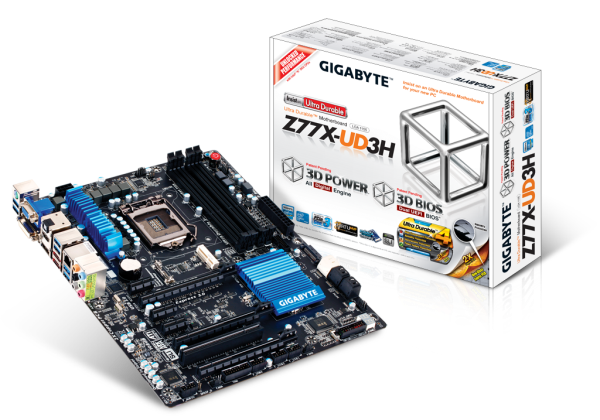
Gigabyte GA-Z77X-UD3H – Overview
For $160, there are a significant number of Z77 motherboards to look at, but Gigabyte wants you to buy theirs. In this case, it is the Z77X-UD3H - their mid range, probably highest selling, Z77 SKU. As a reviewer, it is important to not solely focus on the high end products, as it is the ones lower down the range that are often the best selling and closer to what people actually get in a system. Too many high-end boards can leave a reviewer out-of-touch to what actually sells.
With the GA-Z77X-UD3H, we have a good priced Z77 board with a myriad a features to tempt users. Gigabyte is pushing their digital power delivery and tweakable power delivery options, but we also have an mSATA port, a very good (and new-ish) automatic overclocking utility, and a cheaper board with all four video outputs. The audio/network controller choice is a little different, and we actually get power/reset buttons on a mid range Gigabyte board.
Overall, I did not come across many things wrong with the board. There are certain areas that could do with a little improvement, such as memory compatibility or fan controllers, but it seems like a user will have to stretch the wallet a bit for them in other products. At $160, the board is definitely probing the lower end of the enthusiast market, so could be ideal for a more budget-oriented build.
Visual Inspection
Black and blue seems to be the order of the day when it comes to mainstream boards, as indicated by some of the previous boards but also with the Gigabyte GA-Z77X-UD3H. Perhaps there is a sale on black PCBs and blue heatsinks?
Joking aside, Gigabyte intends to release two high-end boards initially – the Z77X-UD5H and the Z77X-UD3H, both in regular and WiFi variants. The WiFi variant comes with a PCIe x1 WiFi card to be used in the first PCIe slot on the board, and aerials for the outside of the case.
We have the Z77X-UD3H in to review for the launch of Ivy Bridge, which should retail for around $160 MSRP. Gigabyte has chosen a few different directions regarding which controllers are on the motherboard. This should provide interesting results when it comes to performance.
The VRM power delivery comes with a relatively small blue heatsink next to the socket. I’ve noticed that Gigabyte tend to have their memory closer to the socket than most other manufacturers, presumably in the name of performance due to shorter interconnects, but the downside is that it can restrict big air coolers. Nonetheless, it all still conforms to Intel specifications, and there is actually a large gap to the south of the socket.
In terms of fan headers, there are only two within reach of the socket. We have a 4-pin CPU header at the top near the memory slots, and another near the power/reset/ClearCMOS buttons at the top right of the board. The other three headers on board are found at the bottom – one 4-pin beside the SATA ports, one 4-pin next to the USB headers and another 4-pin beside the TPM.
Along the right hand side of the motherboard, Gigabyte has given us a different style of power/reset/clear CMOS button that I have seen before. The power button is big and red, whereas the other two are relatively small. These will be of use to reviewers and overclockers, however having the ClearCMOS the same size and shape as the reset button may lead to several bad fumbling for the right button followed by several four-letter expletives.
Further down is another style choice – an additional power connector for the PCIe and system, but this case it is a SATA power connector. I prefer this to the awkward molex connectors we see on other products. Below this are the standard six SATA ports from the PCH – two SATA 6 Gbps and four SATA 3 Gbps. Below this is the handy two-digit debug display.
Along the bottom of the board, from left to right, we have the front panel audio, SPDIF header, a 4-pin fan header, the TPM header, three USB 2.0 headers, and another fan header. At the top of the PCIe is our mSATA connection, useful for mSATA SSDs and boot drives to save case space. In terms of PCIe, Gigabyte has installed a little nugget of common sense, giving enough space between the first two full-length PCIe for GPUs. However, in the x1, x16 (x8 in multi-GPU), x1, x1, x8, PCI, x4 setup, only the first two full length PCIe are for graphics output – the final one is a PCIe 2.0 x4 connector. This would be better served if it were a slightly different color to the other PCIe x16/x8 connectors. Also with two full length GPUs on board, the user will have access to two PCIe x1 connectors but the PCI connector is blocked.
I know Gigabyte will make a few people jump with joy in relation to the back panel layout – no USB 2.0! From left to right, we have a PS/2 combination port, two USB 3.0, D-Sub, DVI-D, an Optical SPDIF output, HDMI, DisplayPort, two more USB 3.0, two eSATA, gigabit Ethernet, a final two USB 3.0, and audio outputs.
Board Features
| Gigabyte GA-Z77X-UD3H | |
| Price | Link |
| Size | ATX |
| CPU Interface | LGA-1155 |
| Chipset | Intel Z77 |
| Power Delivery | 6 + 4 |
| Memory Slots |
Four DDR3 DIMM slots supporting up to 32 GB Up to Dual Channel, 1066-1600 MHz |
| Video Outputs | DisplayPort, HDMI, DVI-D, D-Sub |
| Onboard LAN | Atheros |
| Onboard Audio | Via VT2021 |
| Expansion Slots |
2 x PCIe x16 Gen3 (x16, x8/8) 1 x PCIe x16 Gen2 (x4) 3 x PCIe x1 Gen2 1 x PCI |
| Onboard SATA/RAID |
2 x SATA 6 Gbps (PCH), Support for RAID 0, 1, 5, 10 4 x SATA 3 Gbps (PCH) 1 x mSATA connector (shared with SATA2_5) 2 x eSATA 6Gbps (Marvell 9172), RAID 0, 1 |
| USB |
Six USB 3.0 at rear (2 PCH, 4 VIA VL800) One USB 3.0 header on board Three USB 2.0 headers on board |
| Onboard |
4 x SATA 3 Gbps 2 x SATA 6 Gbps 1 x mSATA Connector 5 x Fan Headers 1 x USB 3.0 Header 3 x USB 2.0 Headers 1 x Front Panel Header 1 x Clear CMOS Button 1 x TPM Header 1 x SPDIF Output 1 x SATA Power Connector |
| Power Connectors |
1 x 24-pin ATX connector 1 x 8-pin 12V connector 1 x SATA Power connector |
| Fan Headers |
1 x CPU Fan Header (4-pin) 4 x CHA Fan Headers (4-pin) |
| IO Panel |
1 x Gigabit Ethernet Audio Outputs 1 x DVI-D 1 x D-Sub 1 x DisplayPort 1 x HDMI 2 x eSATA 6 Gbps 1 x Combo PS/2 Port 6 x USB 3.0 1 x Optical SPDIF Output |
| Warranty Period | 3 Years |
| Product Page | Link |
One of the odd choices of Gigabyte is their network and audio controllers. On nearly every board I have reviewed, we get either a Realtek, an Intel or a Broadcom for the network, and a Realtek or Creative audio solution. Gigabyte has decided to jump in with an Atheros network controller, and a Via VT2021 audio. It will be interesting to see if this has an effect on our test capabilities.
Gigabyte GA-Z77X-UD3H - BIOS
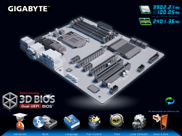
Gigabyte BIOSes have been a little up and down of late. When every other manufacturer was displaying their graphical BIOS systems with P67 and Z68, Gigabyte still had a basic system reminiscent of the previous 10 years of BIOSes. With X79 they introduced a graphical BIOS, termed '3D BIOS'. This was essentially a perspective image coupled with a range of BIOS options.
Since then, we have the next iteration of this '3D BIOS Technology'. From the outset, it looks shaper, sleeker and a refined version of the initial X79 launch. Gigabyte says that their BIOS system is completely bespoke, written from the ground up rather than an interface on a licensed system like other competitors. While this introduces a level of infancy to the system compared to others that have been using licensed back ends for a while, it should offer Gigabyte a wider range of maneuverability in terms of what fancy features they can offer.
In terms of design choices, Gigabyte have decided to use a generic outlay of most of the Z77 range with this screenshot - you will notice the PCIe layout is not the same. However, this does not matter much - by moving the mouse over any of the components in the image (CPU, Power Delivery, and IO) will bring up an explanation of the part, and clicking will give a variety of options. As a front screen, it would help if it stated the model of the motherboard being probed, the CPU, and the amount of memory. Other vendors have voltages and fan speeds as well - by going through this sort of layout, Gigabyte have essentially boxed themselves out of providing this information without some serious design changes to be made.
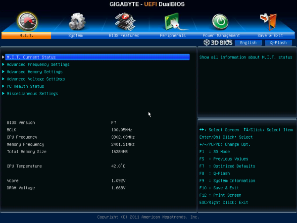
The buttons at the bottom of this 3D BIOS screen offer some other choices - boot sequence, languages, fan controls, and a quick save and exit. However, the 'Advanced' mode brings up the set of BIOS controls that allow for a greater choice and flexibility:
As a bonus compared to X79, this BIOS interface is a lot quicker. Previously, in order to use the number pad to insert values, the user would have to press Num Lock, wait five seconds for it to initialize, and then values could be entered. This time it works straight from the off. Most options will allow users to click and select values as well.
For overclocking, our options are split over many menus (which could be seen as a little annoying). For CPU and memory frequency settings, the 'Advanced Frequency Settings' option comes into play, which also allows modification of Turbo modes and power limits. The more advanced memory settings, such as subtimings, can be modified in the Memory menu. The 'fun' comes from the voltage settings screen, which has a different screen for CPU and Memory voltages, and then a third screen for customizing the digital power delivery options. 99.99% of users will never need the digital power delivery options though.
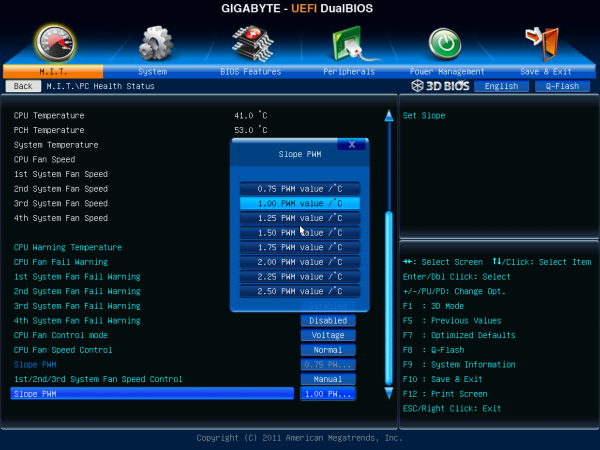
Fan controls come under the PC Health menu as per usual, and Gigabyte are still deciding to stick with an almost incomprehensible method of allowing users to customize their fan settings. By offering options in 'PWM Value / ºC', the only thing the user will understand is 'more means more power'. I would rather this actually had temperatures related to it, or some sort of in-BIOS graphing system to show what is actually happening.
In other Gigabyte BIOS related news, I had distinct trouble trying to get any G.Skill memory to boot on the shipping (F2) BIOS. It would simply keep resetting the board. In the end, I had to use some older Patriot memory to install a newer BIOS (F7) and then tried with the G.Skill again, with success.
Software
Gigabyte software takes a pinch of the old and a pinch of the new(ish). As the backbone, we still have EasyTune6, the all-in-one overclocking and monitoring tool. Although it looks weathered with age, with a decent upgrade (ET7?) it could be back on its feet. It certainly needed it with the version that came on the disk with the motherboard:
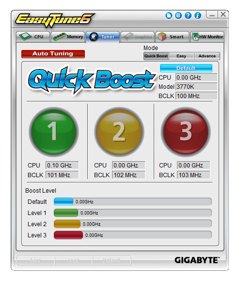
The version as shipped could not read the CPU properly, or suggest overclocks for it. I attempted to download the latest version from Gigabyte, only for it to be corrupt no matter where I downloaded it. However, I would expect it to be fixed as soon as possible - I have seen screenshots from overclockers using versions that work, so no doubt that will filter down to the public through the download website.
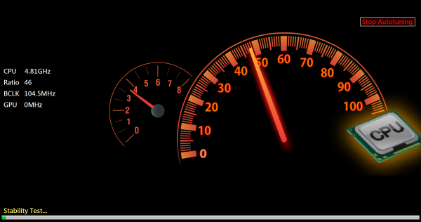
EasyTune6 has its usual gamut of basic and advanced overclocking options, as well as a hardware monitor and a very basic fan control front end. What is relatively new about ET6 is its auto-tuning feature. The red button on the screen above releases Gigabyte's new tuning feature for Ivy Bridge systems:
After confirming you wish to proceed, it does a series of stability tests with CPU ratios and BCLKs. It overall worked like a charm - I cannot fault it. With my processor, it kept all the turbo modes, but gave the processor a 4.81 GHz overclock under single threaded performance, reducing to 4.59 GHz for multithreaded loads, all at 1.236 volts at load. More about this in the overclocking section on the next page!
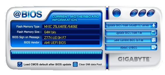
Gigabyte also bundle @BIOS with their motherboards, which allows the user to download and update the latest BIOS (or update from a file) from the operating system.
Gigabyte GA-Z77X-UD3H - In The Box
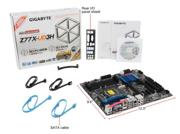
Over the past several motherboard generations, I have not been that impressed with Gigabyte's offering in terms of extras - this is because in order to hit a price point, sometimes the extras in the box are not the focus of the product. With the Z77X-UD3H, we are hoping for at least some good stuff here.
Driver CD
User Manual
IO Shield
Four SATA Cables
One long SLI bridge
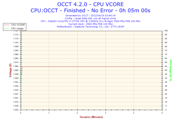
Voltage Readings
Using OCCT we monitor the voltage change of the motherboard under load. This represents the direct correlation between the Load Line Calibration and how the processor/motherboard deals with voltage requests while under load. This is not to be confused with the quality of power delivery, but more an indication of how aggressive the default LLC settings are on a motherboard.
The response of the Gigabyte board under load is fantastic. No ripple at all and a lower average voltage than the ASUS P8P77-V Pro.
Overclocking
Note: Ivy Bridge does not overclock like Sandy Bridge. For a detailed report on the effect of voltage on Ivy Bridge (and thus temperatures and power draw), please read Undervolting and Overclocking on Ivy Bridge.
The Gigabyte GA-Z77X-UD3H has a variety of overclocking tools at the disposal of the user. Automatic overclocks are through EasyTune6, where we experienced a rather good result with our chip with Gigabyte's auto tuning software, and manual overclocks are either performed through the BIOS (with a series of menu jumps which should have been more carefully laid out), or using a new Gigabyte tool called TweakLauncher. I have not previewed TweakLauncher here, as it is primarily for sub-zero overclockers wanting real-time access to changes in performance while under extreme temperatures. It forgoes the usual GUI interface and sliders with something more amenable to the competitive overclocker - it is not suitable for the majority of users.
Auto Overclock: Using the Auto Tuning option in EasyTune6, the software pulled up a large screen and offered a confirmation of a stress-tested overclock. When clicked yes, the system would stability test a range of BCLK and Multipliers until the board resets or the system finds it unstable. When this had finished, the board offered me a 46x104.5 overclock (4810 MHz). I discovered that turbo modes still applied, so this speed was the single thread speed, and the CPU would reduce the multiplier by two for multithreaded loads, giving 4589 MHz). This gave 1.236 volts at load, which could be a little high, but due to the lower speed under multithreaded load, the CPU only reached 84ºC under PovRay and was completely stable. I enjoyed this result a lot from an automatic overclock!
Manual Overclock: Due to the way Ivy Bridge behaves with increased voltage, for a manual overclock, I am testing the peak overclock at a variety of voltages as well as the temperatures at that voltage. On the Gigabyte board, the CPU load line calibration was set to Extreme and Intel Speed Step was disabled. One interesting thing to note was that Gigabyte set this board to 100.9 MHz default on the BCLK, rather than 100.0 MHz. When the multiplier is pushed above 44x, this is reduced to 100.0 MHz.
At 1.100 volts, the highest multiplier that was stable was 45x, giving 4.5 GHz. This gave 70ºC at load with PovRay, and showed a load voltage of 1.116 volts.
At 1.150 volts, the highest multiplier that was stable was 46x, giving 4.6 GHz. This gave 75ºC at load with PovRay, and showed a load voltage of 1.164 volts.
At 1.200 volts, the highest multiplier that was stable was 47x, giving 4.7 GHz. This gave 82ºC with PovRay, 86ºC with OCCT, and a load voltage of 1.212 volts.
At 1.250 volts, the board successfully booted at 4.8 GHz, with 1.272 volts under load and 89ºC with PovRay - but this was not stable due to the memory errors in PovRay, suggesting more voltage is required. Given the current load temperature, I was unwilling to push the voltage further.
In terms of memory, when attempting to overclock a G.Skill 2x4 DDR3-2666 kit, which performed 2950 MHz on the ASUS P8Z77-V Pro, it would not boot at the DDR3-2800 strap despite all the correct timings being entered.
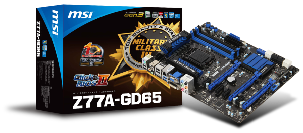
MSI Z77A-GD65 - Overview
Whenever it comes to a motherboard comparison involving ASUS, Gigabyte or ASRock against an MSI board, the MSI board always tends to show a strong result - either in terms of price, performance or features. Therefore, when it comes to the new batch of motherboards for Ivy Bridge, it is fair to say that I expect a strong showing from MSI. Today, we have their Z77A-GD65, which will be one behind their future released GD80 that got attention back at CES for being Thunderbolt equipped.
The Z77A-GD65 currently retails at $190, a good amount above the Gigabyte board. With the MSI, we have an Intel NIC, a full set of audio outputs, but no PCI or mSATA. The Z77A-GD65 is in general a good board to play with. It would underpin any Z77 build with ease. The design is beneficial to multi-GPU setups, offers voltage read points of overclockers, and gives a front facing USB 3.0 port for front panel USB 3.0 cases. The auto-overclocking OC Genie is relatively simple, but using the BIOS is straightforward (either at boot time or in the OS with Click BIOS software) to get something more befitting an Ivy Bridge processor.
Due to some of the other boards providing an overclock out-of-the-box, performance on the MSI may seem to be a little down on the other boards, but by enabling OC Genie on board, which every processor should be able to do, performance numbers would be comparable to the competition.
Visual Inspection
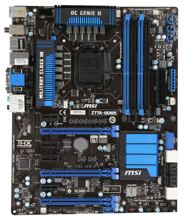
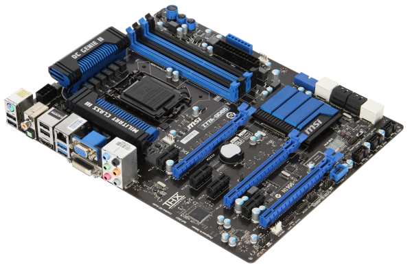
The Z77A-GD65 is another motherboard in this roundup that comes in a black and blue livery. This time MSI have more of an excuse than others do as they have been using it for a fair while now. Using what is essentially a 10 + 2 phase power delivery, MSI are using somewhat beefier heatsinks than their rivals, connecting both via a heatpipe. The socket area is right up against Intel's minimum requirements from left to right, but there is some room to maneuver big air coolers from top to bottom. Around the socket there are at least four fan headers to use: one 4-pin CPU header between the top VRM and the memory slots, a 4-pin system fan header just the other side of the memory slots, a 4-pin to the bottom left of the socket area, and another 4-pin beside the 24-pin ATX power connector. A fifth fan header can be found at the bottom of the board.
Along the right hand side, we have the standard MSI trio of power/reset/OC Genie buttons, followed by a series of voltage checkpoints for overclockers. Aside from the 24-pin power connector and the system fan header, there is also a USB 3.0 header at right angles to the board, indicating its primary use is to the front of the case. Underneath this are the eight SATA ports - two SATA 6 Gbps from the PCH, four SATA 6 Gbps also from the PCH, and another two SATA 6 Gbps from an ASMedia controller.
As the power/reset/OC Genie buttons are at the top right, the bottom of the board has more room to fit in all the headers as needed - front panel audio, TPM, front panel headers and USB 2.0 headers. In terms of PCIe, MSI have done away with the PCIe to PCI bridge and focused purely on PCIe. We have an x1, x16 (x8 with dual GPU), x1, x1, x8, x1, and a PCIe 2.0 x4. In this instance, there is plenty of room for a dual GPU setup with PCIe slots to spare for any extras.
Also of note is the chipset cooler, which is very flat and large with minimal fins, perhaps suggesting that MSI is confident about their heatsink design. Underneath this is a two digit debug display, and a BIOS switch for changing between two BIOSes.
On the rear IO panel, I think MSI have been reasonable with what they have left in and what they have left out. From left to right, we have a combination PS/2 port, two USB 2.0 ports (black), a clear CMOS button, digital and coaxial SPDIF outputs, two more USB 2.0 ports (black), a HDMI port, gigabit Ethernet, two USB 3.0 ports (blue), D-Sub, DVI-D, and audio jacks.
Board Features
| MSI Z77A-GD65 | |
| Price | Link |
| Size | ATX |
| CPU Interface | LGA-1155 |
| Chipset | Intel Z77 |
| Power Delivery (CPU/iGPU) | 8 + 1 + 2 + 1 (VRM/VTT/GPU/SA) |
| Memory Slots |
Four DDR3 DIMM slots supporting up to 32 GB Up to Dual Channel, 1066-2667 MHz |
| Video Outputs | HDMI, DVI-D, D-Sub |
| Onboard LAN | Intel 82579V |
| Onboard Audio | Realtek ALC898 |
| Expansion Slots |
2 x PCIe x16 Gen3 (x16, x8/8) 1 x PCIe x16 Gen2 (x4) 4 x PCIe x1 Gen2 |
| Onboard SATA/RAID |
2 x SATA 6 Gbps (PCH), Support for RAID 0, 1, 5, 10 4 x SATA 3 Gbps (PCH), Support for RAID 0, 1, 5, 10 2 x SATA 6 Gbps (ASMedia ASM1061) |
| USB |
4 USB 3.0 ports (2 back panel, 2 from headers) 10 USB 2.0 ports (4 back panel, 6 from headers) |
| Onboard |
4 x SATA 6Gbps 4 x SATA 3 Gbps 1 x USB 3.0 Header 3 x USB 2.0 Headers 1 x IEEE1394 Header 1 x TPM Header 1 x Front Panel Audio Header Power/Reset Buttons OC Genie 5 x Fan Headers |
| Power Connectors |
1 x 24-pin ATX connector 1 x 8-pin 12V connector |
| Fan Headers |
1 x CPU Fan Header (4-pin) 4 x SYS Fan Headers (two 4-pin, two 3-pin) |
| IO Panel |
1 x Combo PS/2 Port 1 x Clear CMOS Button 1 x Coaxial S/PDIF Port 1 x Optical S/PDIF Port 4 x USB 2.0 2 x USB 3.0 1 x Gigabit Ethernet Audio Jacks 1 x HDMI 1 x DVI-D 1 x D-Sub |
| Warranty Period | 3 Years |
| Product Page | Link |
It is good to see an Intel NIC on this motherboard and plenty of headers to go around. The only things missing where other motherboards may have better all-round functionality are a PCI slot, mSATA or on-board WiFi.
MSI Z77A-GD65 - BIOS
MSI's graphical BIOS was the result of an internal design competition - given various intricacies and factors in the final designs, the one that came 3rd went on to be the graphical interface we see today. Over the past few generations, I have been either critical of MSI with their P67 'BIOS games' (explained to me later as more of a technical showcase), or appreciative of their X79 revision.
The BIOS on Z77 is the same as the X79 version. Despite making several suggestions regarding that BIOS, none seem to have come through, so if I may I would like to make them again. Do not get me wrong, the BIOS is well designed and easy to use - it is just that it could perhaps be easier, especially for overclocking.
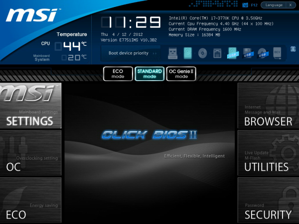
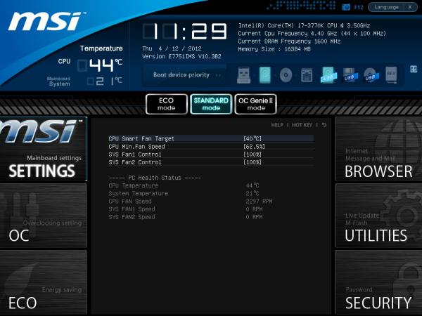
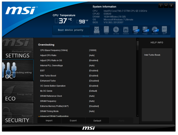
The front page is great - we have CPU and system temperatures, CPU model, and speed, memory speed, memory size, BIOS version, and a boot order at the top. What is great about this is that the top bar (and side navigation tools) are persistent throughout the BIOS, never once disappearing. This layout is great, and would be beneficial if we ever get an increase in BIOS resolution in the future so more information can be put into the center console.
One recommendation is an improvement of the PC Health screen, which should offer lists of voltages and such for different components. Perhaps a few more temperature sensors on board and a better fan control would not go amiss in the future.
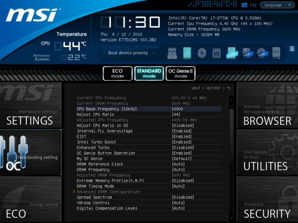
For overclocking, our gaze turns to the OC menu, which essentially lumps all the overclocking options together. There are a couple of issues with this.
Ideally, it should be separated cleanly into CPU, memory, and others, with the CPU voltage in the CPU section and so on. As it currently stands, everything is in one run on menu - if they reduced the font size a little and could do CPU options on the left, memory options on the right, this would be great.
You may notice the Enhanced Turbo feature in the BIOS. This does similar things to ASUS' MultiCore Enhancement, in that the CPU is pushed to 3.9 GHz during full load, 200 MHz more than what it should be. By default, MSI has this off (I criticized them about it on X79), so they naturally have a disadvantage in the benchmarks later on. However, this is the right way to do it - having it enabled by default technically invalidates the warranty on the processor.
Load Line Calibration on MSI boards is hidden under VDroop Control, and other options such as Digital Compensation Level, CPU Core OCP Expander and CPU Core Engine Speed are not properly defined for users. Overall, I really like MSI's BIOS and it has a much nicer feel to it than many of their competitors.
Software
The main gamut of MSI's software comes in three programs - Control Center, Live Update, and Click BIOS.
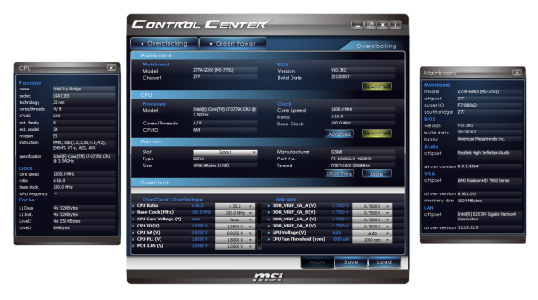
Control Center: At the heart of the operation is Control Center. This piece of software allows for OS adjustments for voltages and fans as well as enabling/disabling the LEDs on the motherboard.
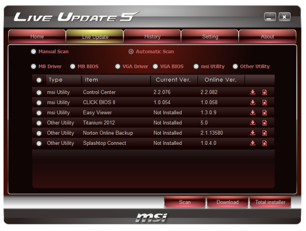
Live Update 5: Best compatibility and the most features usually come from the latest versions of software - so MSI include their Live Update program with their motherboards. This probes the system for software versions (and BIOS versions) then communicates to an online server to suggest updates and new downloads. This is good, with one flaw - when you download new drivers, it does not tell you how big they are. So if you end up having to download 130 MB of new audio drivers on a slow connection, the user will not know until it chugs along at 5% a minute. It is a minor update I hope to see in a later revision.
Click BIOS II:The main software that MSI likes to push is Click BIOS - an operating system based interface for all BIOS modifications. It is designed to look and feel like the actual BIOS, with all the settings. For the most part, this is true - it does initially look like the BIOS, though there are still issues with fonts. With it being an OS utility, they also miss a beat in providing additional tools for settings, such as graphs to manipulate the fan headers.
MSI Z77A-GD65 - In The Box
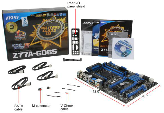
The MSI Z77A-GD65 is currently available for $190, just north of the Gigabyte board. With this in mind, we also get a few more extras in the box than the Gigabyte:
IO Shield
Driver CD
User Manual
Certification of Military Class testing (FWIW)
Four SATA cables
Flexi-SLI bridge
M-Connectors (to help front panel connections)
V-Check cables (to help with voltage read points)
Voltage Readings
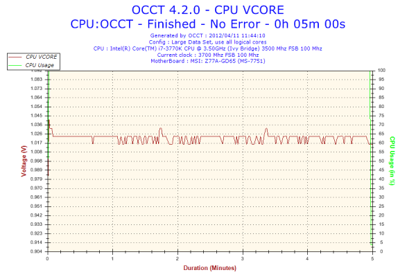
Using OCCT we monitor the voltage change of the motherboard under load. This represents the direct correlation between the Load Line Calibration and how the processor/motherboard deals with voltage requests while under load. This is not to be confused with the quality of power delivery, but more an indication of how aggressive the default LLC settings are on a motherboard.
Similarly to the ASUS board in this review, the MSI has minor variations in the CPU voltage. Worthy of note though is the lower VCore used by the MSI board compared to the other boards in this review while at load, suggesting more aggressive LLC settings.
Overclocking
Note: Ivy Bridge does not overclock like Sandy Bridge. For a detailed report on the effect of voltage on Ivy Bridge (and thus temperatures and power draw), please read Undervolting and Overclocking on Ivy Bridge.
Overclocking options on the MSI Z77A-GD65 are relatively straightforward. With the OC Genie button on board, give it a press and it lights up, causing the next boot to initialize a series of predefined settings for an overclock. Manual overclocks can be done by the Click BIOS software in the operating system, or by adjusting the BIOS directly.
Automatic Overclocking: After pressing the OC Genie button, it essentially seemed to enable the Enhanced Turbo option in the BIOS. The system booted without issue, and I was greeted with a 39x multiplier under all loads, showing 1.080 volts and 65ºC with PovRay. This is a rather disappointing automatic overclock. This is also indicative of issues relating to one button overclocks - the manufacturer is supplying a series of presets that has to work on every processor out of the factory. It is perhaps time that MSI introduces their own stress-testing overclock into the mix to get a better result.
Manual Overclock: Given the previous overclocking results achieved, with the MSI board we jumped straight in with 1.2 volts, with PLL Overvoltage enabled just for good measure. At this voltage, 46x multiplier was the highest multiplier stable, giving 82ºC with PovRay and showing 1.184 volts at load. In order to get the 47x multiplier to work, it required 1.250 volts on the CPU, although this gave 90ºC during PovRay and 1.240 volts at load.
Updates to our Testing Methodology
In light of various requests and as a naturally evolving process, some of our motherboard tests have changed. This has the unfortunate consequence of making many of our previous results incomparable, but if they were never updated, we would still be on Catalyst 6.3 or something similar! Also with experience allows us to pick tests that are able to run and give a nice score without having to sit with a stopwatch for twenty minutes each time.
For our CPU tests, we introduce Xilisoft Video Converter, a tool used to convert one type of video to another. What I like about XVC is that it works using all threads available as much as it can, and if you have a GPU that is compatible, it will use it to help speed up conversion. We also add in x264 HD Benchmark, a standard video encoding benchmark that a few other review websites use.
For the system benchmarks, we utilize two new features for USB testing. In terms of hardware, we use a SATA 6 Gbps to USB 3.0 device connected up to an OCZ Vertex3 240 GB drive in order to really stress both USB 2.0 and USB 3.0. For this test, we are also using software called DiskBench - a utility that records accurate times to copy from one drive through the USB to another.
Our GPU test suite also gets a bump. Previously all benchmarks were run at 1920x1080, a reasonable gaming screen size. Today we move all our benchmarks up to 2560x1440 using a 27" Yamakasi Catleap Q270 LED, a common Korean gaming monitor. In terms of actual GPUs, we are retiring our now two generations old HD 5850s, and with many thanks to ASUS, now using a set of HD 7970s for up to four-way CrossFireX (should the motherboard allow it). For NVIDIA, we still use a pair of ECS GTX 580s for SLI testing. The games are also changing with AVP becoming a relatively trivial (120 FPS+) benchmark at 1920x1080, so we are replacing it with Civilization 5 at 2560x1440.
Test Setup
| Processor |
Intel Core i7-3770K ES 4 Cores, 8 Threads, 3.5 GHz (3.9 GHz Turbo) |
| Motherboards |
ASRock Z77 Extreme4 ASUS P8Z77-V Pro Gigabyte GA-Z77X-UD3H MSI Z77A-GD65 |
| Cooling | Intel All-in-One Liquid Cooler |
| Power Supply | OCZ 1250W Gold ZX Series |
| Memory |
GSkill RipjawsZ 4x4 GB DDR3-2400 10-12-12 Kit GSkill TridentX 2x4 GB DDR3-2666 11-13-13 Kit |
| Memory Settings | XMP (1866 9-10-9) |
| Video Cards |
ASUS HD7970 3GB ECS GTX 580 1536MB |
| Video Drivers |
Catalyst 12.3 NVIDIA Drivers 296.10 WHQL |
| Hard Drive | Micron RealSSD C300 256GB |
| Optical Drive | LG GH22NS50 |
| Case | Open Test Bed - CoolerMaster Lab V1.0 |
| Operating System | Windows 7 64-bit |
| SATA Testing | Micron RealSSD C300 256GB |
| USB 2/3 Testing | OCZ Vertex 3 240GB with SATA->USB Adaptor |
Many thanks to...
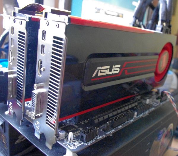
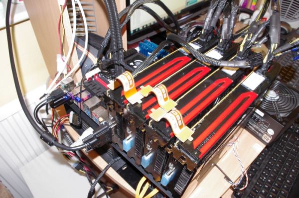
Many thanks to ASUS as they have kindly allowed us to retire our now two generations old HD 5850s. By providing us with a set of ASUS HD 7970s for up to four-way CrossFireX, we can really test any system that comes our way (coupled with that 2560x1440 monitor).
The ASUS HD7970-3GD5 was ASUS' first 7970 product on the market, using the reference design but being coupled with ASUS GPU Tweak software and support. These cards offer solid performance, and I have easily overclocked them from 925/1375 to 1200/1800 with small bumps in voltage. With any luck, the limiting factor for the next few generations of motherboards will be the motherboard rather than our GPU in the GPU testing, as well as some special X79 boards we are testing soon.
A little preview of some overclocking I have done with these cards for a future review
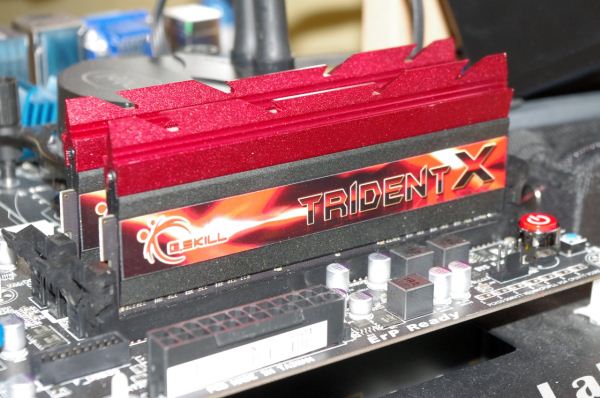
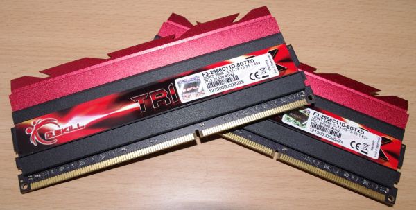
Many thanks should also go to G.Skill, for sending us one of their new TridentX memory kits designed specifically for the Z77 Platform. The kit they have sent is the F3-2666C11D-8GTXD, or put simply, a dual channel 8 GB kit (two 4 GB modules) designed to run at DDR3-2666 MHz with 11-13-13-35 timings at 1.65 volts.
Having DDR3-2666 memory does seem a little far-fetched, given that Panther Point and the CPUs are only rated up to DDR3-1600. However, with the integrated memory controller on Ivy Bridge, most motherboards should support up to DDR3-2666 to DDR3-2800 by default. In the real world, this means that bulk memory transfers, or memory transfer limited situations, should get a boost. This is in the realm of video processing, or integrated graphics gaming, or multi-monitor gaming (depending on how the game is processed). However, given that motherboard manufacturers are releasing the fact that their motherboards should support these high frequencies, it does not hurt to test them!
In terms of G.Skill’s part in all this – their TridentX range will cover dual channel kits and quad channel kits, from 2x4 GB kits, 2x8 GB kits, 4x4 GB kits and to 4x8 GB kits. The smaller 4 GB module kits will have speeds from 2400 to 2800 MHz, and are assured to be competitively priced, as well as overclockable. In terms of our 2x4 GB 2666 11-13-13 kit, we were able to bump up the ratio to 2800 MHz without any change of voltage or subtimings. With a little voltage push, we were able to go to 2950 MHz with some frequency adjustments. As long as the CPU can take it, it seems that G.Skill have some overclockable kits ready for the taking.
Power Consumption
Power consumption was tested on the system as a whole with a wall meter connected to the OCZ 1250W power supply, while in a dual 7970 GPU configuration. This power supply is Gold rated, and as I am in the UK on a 230-240 V supply, leads to ~75% efficiency > 50W, and 90%+ efficiency at 250W, which is suitable for both idle and multi-GPU loading. This method of power reading allows us to compare the power management of the UEFI and the board to supply components with power under load, and includes typical PSU losses due to efficiency. These are the real world values that consumers may expect from a typical system (minus the monitor) using this motherboard.
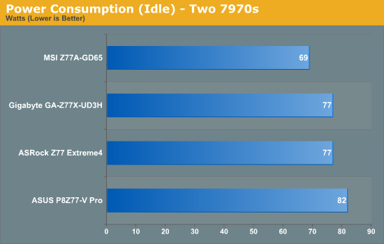
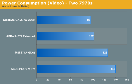
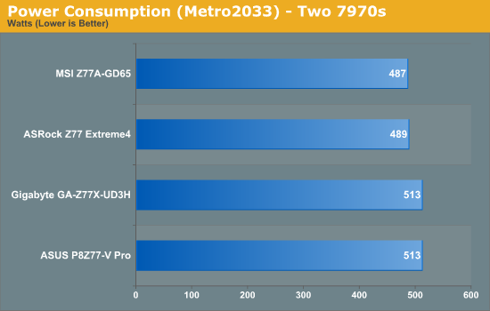
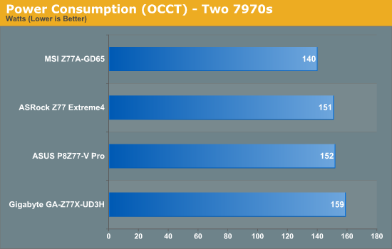
Perhaps the alarming graph of these is the power draw under video performance. It seems that certain motherboard BIOSes consider it a more intensive task, waking up more of the processor (or GPU) to compensate. At load however, we see the MSI and the ASRock boards drawing less power overall.
Boot Times
Different motherboards have different POST sequences before an operating system is initialized. A lot of this is dependent on the board itself, and POST boot time is determined by the controllers on board (and the sequence of how those extras are organized). As part of our testing, we are now going to look at the POST Boot Time - this is the time from pressing the ON button on the computer to when Windows starts loading. (We discount Windows loading as it is highly variable given Windows specific features.) These results are subject to human error, so please allow +/- 1 second in these results.
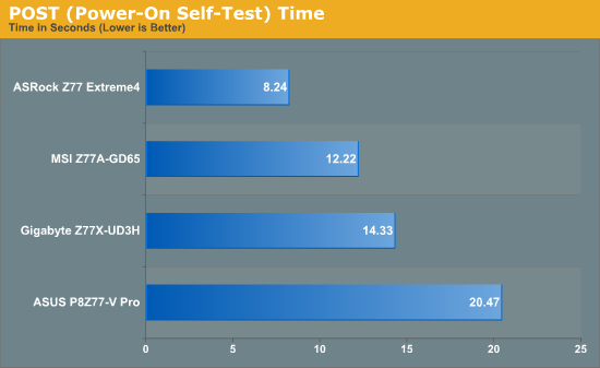
With a lot more controllers to initialise on board, the ASUS P8Z77-V Pro requires at default 20.47 seconds to reach the windows loading screen. By disabling controllers that aren't used, a time more like the ASRock could be achieved. There is direct correlation between functionality and POST time.
Overclocking
Here at AnandTech we want to provide quick and easy ways to determine if a board is good for you (with in-depth analysis of course). So here is a quick round up of our overclocking results. Overclocks are tested for stability with PovRay and OCCT - while these may not be the most strenuous of stability tests, it does offer a quick check for memory errors under high load (and also balances testing time with getting the next board on for review!).
|
CPU Speed (MHz) |
Voltage (Volts) |
PovRay Peak Temp (ºC) |
OCCT Peak Temp (ºC) |
Notes | |
|
ASRock Z77 Extreme4 |
4700 | 1.175 | 86 | 86 | LLC Level 1 |
|
ASUS P8Z77-V Pro |
4700 | 1.200 | 83 | 86 | PLL Overvoltage enabled |
|
Gigabyte Z77X-UD3H |
4700 | 1.200 | 82 | 86 | LLC Extreme |
|
MSI Z77A-GD65 |
4700 | 1.250 | 90 | - | PLL Overvoltage enabled |
LAN Speed Test
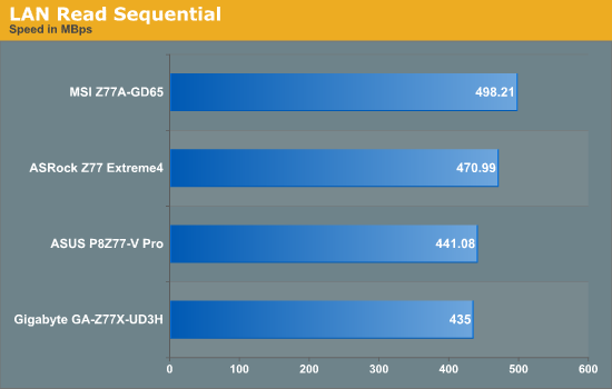
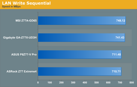
LAN Speed Test is a freeware program designed for testing the network connection between two PCs on a home network. The speed of the transfer is limited by the lowest common denominator on the network, so if you have gigabit Ethernet capable computers but a 100 Mbit capable router, you are limited to 100 Mbit transfer. Note that this is really a formality – if a network port is rated at 1 Gbps, then chances are that it might hit at least 90+% of this value. The main test here is CPU usage, and how much is offloaded by the controller. For this test, we use LAN Speed Test to transfer a 1000 x 1 MB files across a home network with a 1 Gbps lowest common speed to the same machine each time, in a read/write scenario. Results are taken as peak speeds from several runs.
USB Speed
For this benchmark, we run CrystalDiskMark to determine the ideal sequential read and write speeds for the USB port using our 240 GB OCZ Vertex3 SSD with a SATA 6 Gbps to USB 3.0 converter. Then we transfer a set size of files from the SSD to the USB drive using DiskBench, which monitors the time taken to transfer. The files transferred are a 1.52 GB set of 2867 files across 320 folders – 95% of these files are small typical website files, and the rest (90% of the size) are the videos used in the Sorenson Squeeze test.
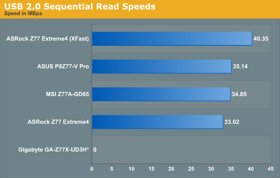
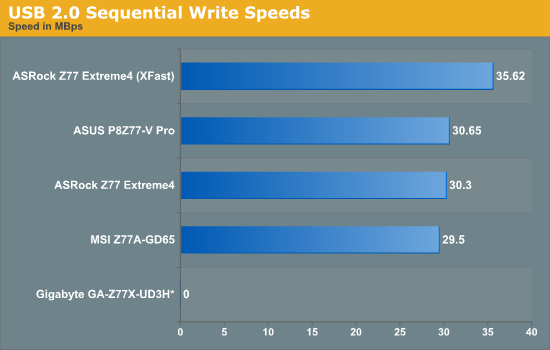
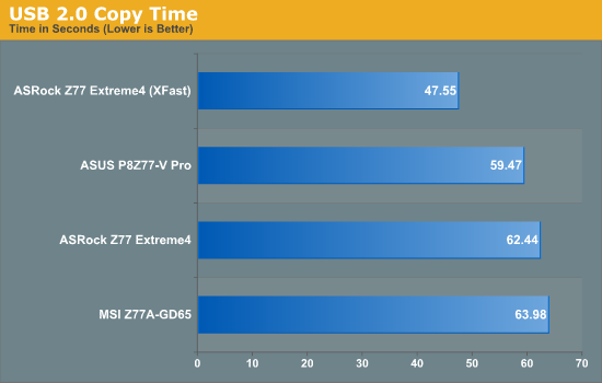
Due to the lack of Gigabyte USB 2.0 back panel ports, no results for the Gigabyte board were able to be fairly taken. In comparison, the XFast result from ASRock seems to speed ahead of the others.
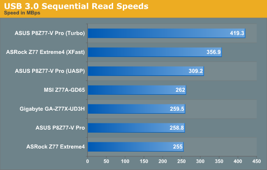
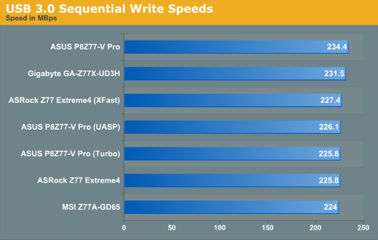
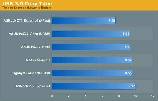
As this test deals with incompressible data at a Queue Depth of 1, UASP makes a difference in read but not in write. The adaptations performed by XFast are clear to see at this level.
SATA Testing
We also use CrystalDiskMark for SATA port testing on a C300 drive. The sequential test (incompressible data) is run at the 5 x 1000 MB level. This test probes the efficiency of the data delivery system between the chipset and the drive, or in the case of additional SATA ports provided by a third party controller, the efficiency between the controller, the chipset and the drive.
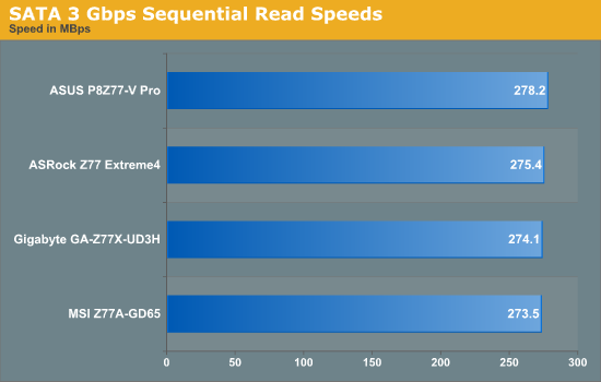
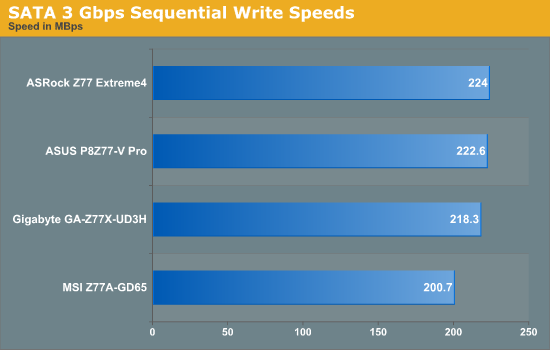
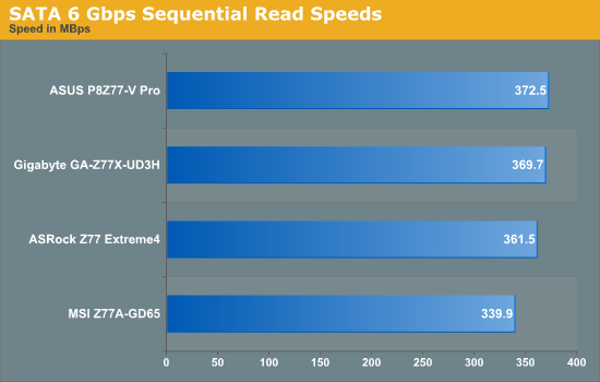
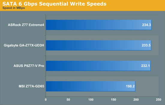
The MSI board seems to come out last in all our SATA testing.
DPC Latency
Deferred Procedure Call latency is a way in which Windows handles interrupt servicing. In order to wait for a processor to acknowledge the request, the system will queue all interrupt requests by priority. Critical interrupts will be handled as soon as possible, whereas lesser priority requests, such as audio, will be further down the line. Therefore, if the audio device requires data, it will have to wait until the request is processed before the buffer is filled. If the device drivers of higher priority components in a system are poorly implemented, this can cause delays in request scheduling and process time, resulting in an empty audio buffer – this leads to characteristic audible pauses, pops and clicks. Having a bigger buffer and correctly implemented system drivers obviously helps in this regard. The DPC latency checker measures how much time is processing DPCs from driver invocation – the lower the value will result in better audio transfer at smaller buffer sizes. Results are measured in microseconds and taken as the peak latency while cycling through a series of short HD videos - less than 500 microseconds usually gets the green light, but the lower the better.
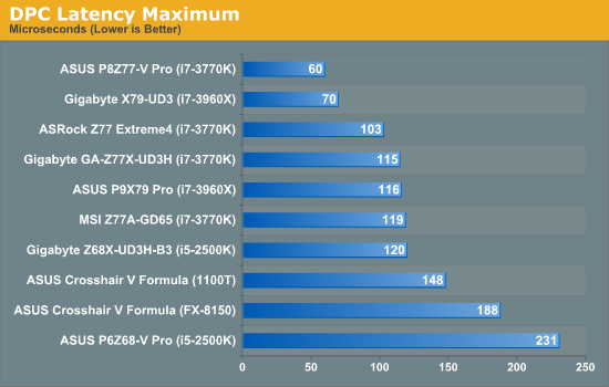
All the motherboards using Ivy Bridge chips do particularly well in our DPC test (as you would expect), with all boards coming in at under a very respectable 120 microseconds. The ASUS goes one step further with our lowest DPC score ever at 60 microseconds.
3D Movement Algorithm Test
The algorithms in 3DPM employ either uniform random number generation or normal distribution random number generation, and vary in various amounts of trigonometric operations, conditional statements, generation and rejection, fused operations, etc. The benchmark runs through six algorithms for a specified number of particles and steps, and calculates the speed of each algorithm, then sums them all for a final score. This is an example of a real world situation that a computational scientist may find themselves in, rather than a pure synthetic benchmark. The benchmark is also parallel between particles simulated, and we test the single thread performance as well as the multi-threaded performance.
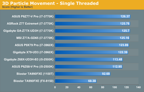
In our single threaded test, the improved IPC from Ivy Bridge is clear to see, with every board able to beat the i7-3960X results.
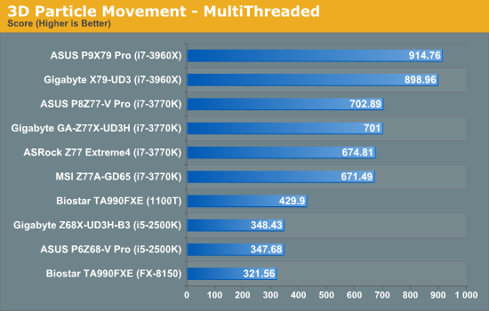
Now we see some real differences to the boards - as the ASUS has MultiCore Enhancement, which boosts the CPU to full turbo mode under multithreaded mode, it has a clear advantage over the other boards in the test. Surprisingly the Gigabyte board also did the same, despite clear settings in the BIOS to enforce multiplier ratios at core loads.
WinRAR x64 3.93
With 64-bit WinRAR, we compress the set of files used in the USB speed tests. WinRAR x64 3.93 attempts to use multithreading when possible.
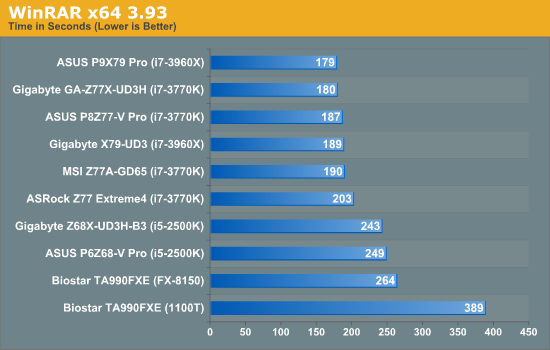
Due to the mixed threaded nature of the WinRar test, this is all about how the board reacts to different load levels. The four core Ivy chips are on par with the six core Sandy-E chips, but the ASRock Z77 seems to lag behind.
FastStone Image Viewer 4.2
FastStone Image Viewer is a free piece of software I have been using for quite a few years now. It allows quick viewing of flat images, as well as resizing, changing color depth, adding simple text or simple filters. It also has a bulk image conversion tool, which we use here. The software currently operates only in single-thread mode, which should change in later versions of the software. For this test, we convert a series of 170 files, of various resolutions, dimensions and types (of a total size of 163MB), all to the .gif format of 640x480 dimensions.
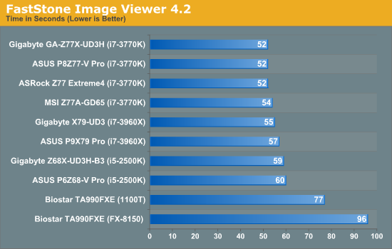
The single thread speed is key for FastStone, where the IPC for Ivy really gets to play.
Xilisoft Video Converter
With XVC, users can convert any type of normal video to any compatible format for smartphones, tablets and other devices. By default, it uses all available threads on the system, and in the presence of appropriate graphics cards, can utilize CUDA for NVIDIA GPUs as well as AMD APP for AMD GPUs. For this test, we use a set of 32 HD videos, each lasting 30 seconds, and convert them from 1080p to an iPod H.264 video format using just the CPU. The time taken to convert these videos gives us our result.
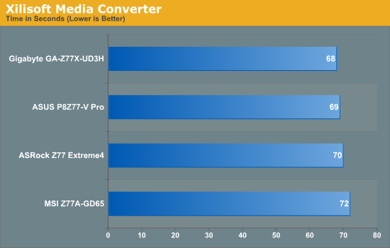
As one of our new tests, Xilisoft can show how motherboards treat a fully multi-threaded load with optimised coding. Again, the ASUS and Gigabyte win out here.
x264 HD Benchmark
The x264 HD Benchmark uses a common HD encoding tool to process an HD MPEG2 source at 1280x720 at 3963 Kbps. This test represents a standardized result which can be compared across other reviews, and is dependant on both CPU power and memory speed. The benchmark performs a 2-pass encode, and the results shown are the average of each pass performed four times.
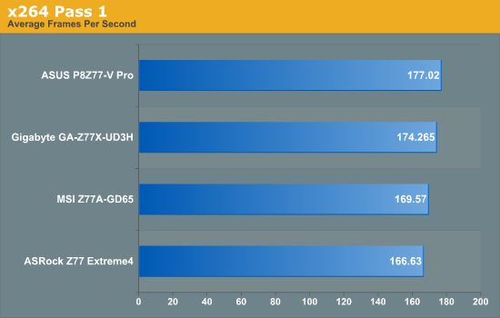
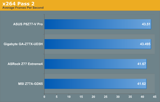
Similarly to Xilisoft, the way different boards react to a full multithreaded load are on display. Score another one for ASUS and Gigabyte.
Civilization V
Civilization V is a strategy video game that utilizes a significant number of the latest GPU features and software advances. Using the in-game benchmark, we run Civilization V at 2560x1440 with full graphical settings, similar to Ryan in his GPU testing functionality. Results reported by the benchmark are the total number of frames in sixty seconds, which we normalize to frames per second.
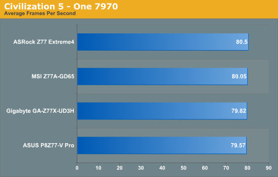
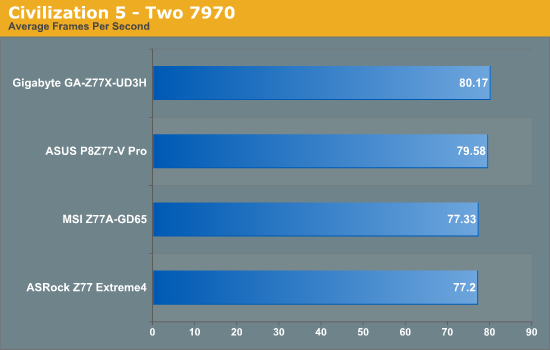
During AMD testing, it is clear that Civilization 5 is not GPU limited at 2560x1440 as CrossFire results are either equivalent to single card testing, or even less than (indicating overhead). The increased multi-threaded speed reduces the overhead in dual GPU mode.
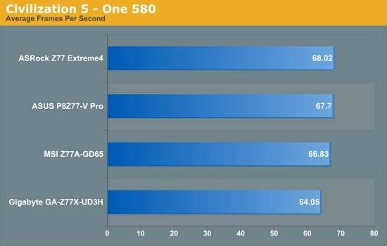
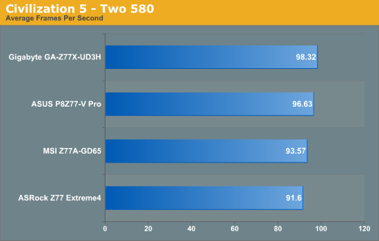
Given the GTX580s are weaker cards (but still powerful), we do see a difference between single GPU and dual GPU for Civilization, with dual GTX580s beating dual 7970s. At dual GPU mode, again the ASUS and Gigabyte perform better than the other two.
Dirt 3
Dirt 3 is a rallying video game and the third in the Dirt series of the Colin McRae Rally series, developed and published by Codemasters. Using the in game benchmark, Dirt 3 is run at 1920x1080 with full graphical settings. Results are reported as the average frame rate across four runs.
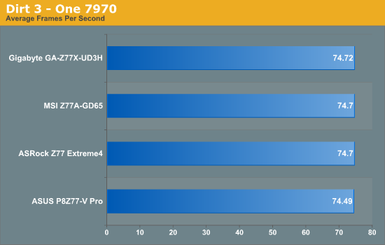
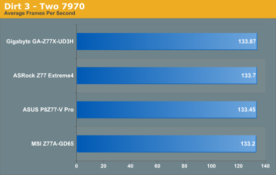
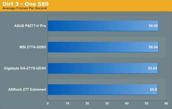
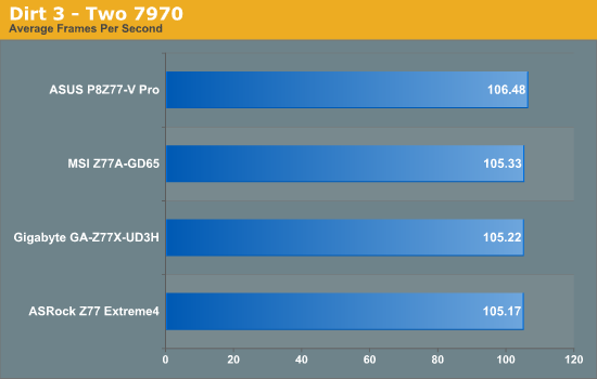
Dirt3 results are very consistent across the board.
Metro2033
Metro2033 is a DX11 benchmark that challenges every system that tries to run it at any high-end settings. Developed by 4A Games and released in March 2010, we use the inbuilt DirectX 11 Frontline benchmark to test the hardware at 1920x1080 with full graphical settings. Results are given as the average frame rate from 10 runs.
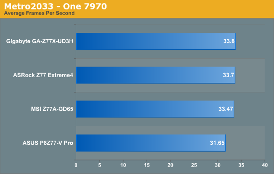
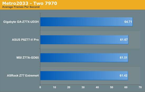
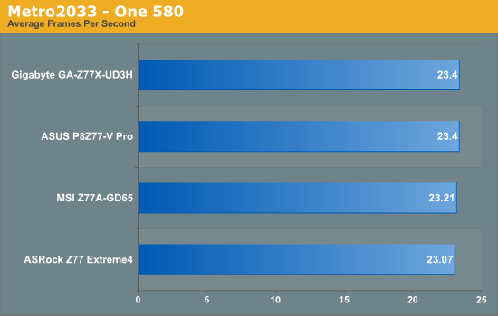
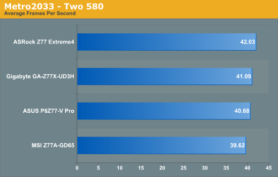
Metro2033 performance seems to vary across the board, where dual GTX580s shows the greatest variation in performance between the boards. We would expect the higher multi-threaded nature of the ASUS and Gigabyte to do well, however it seems Metro2033 involves more than pure CPU speed.
Conclusion – ASRock Z77 Extreme4
I had high expectations of the ASRock product due to what we have seen in previous chipsets. Over time, they have developed this knack of offering a good performance product at a great price, and a large amount of free kit in the box to sweeten the deal.
The Z77 Extreme4 is the lower end enthusiast board coming out from ASRock at release (compared to a total 20 models listed on their website). Therefore, when it comes in at $135, we should like this price. In the box is not substantial, with just a pair of SATA cables and an SLI finger, but we are treated to the ASRock BIOS and Software package. The big addition on the package is the Internet Flash software, allowing users to update their BIOS to the latest without needing to download it in an Operating System.
Performance wise, ASRock seem to be lacking the enhanced Turbo option utilized by other motherboard manufacturers by default, so we may see it in future BIOS builds. The XFast LAN software also shows superior performance in incompressible transfers or real-world transfers compared to standard USB throughput.
By making this board a little bit smaller than ATX, this board is cheaper than the rest and I really like the styling. As long as you remember to adjust the default CPU fan speed, this inexpensive board would be a good choice for an Ivy Bridge build.
Conclusion – ASUS P8Z77-V Pro
Whenever a reviewer deals with a variety of products at different price points, thoughts go through the mind of a reviewer about where that additional money has gone. If you look at an ASUS board, the usual culprits pop up - vastly improved fan controls, superior BIOS and software, digital power delivery, and a general feel that the board is solidly built. ASUS has gone another step further with their Z77 range, and on the Pro this means an Intel NIC as standard, onboard WiFi, USB Flashback, all four Ivy Bridge video outputs available, USB 3.0 Boost, Q-LED for POST diagnosis, and even a Thunderbolt header which connects to a future ASUS Thuderbolt add-in card (sold separately).
Performance on the P8Z77-V Pro is bolstered by the MultiCore Enhancement BIOS setting, which invokes maximum turbo mode for any core loading by default giving multi-threaded results an advantageous score. I feel this sort of setting will quickly become the standard, as motherboard manufacturers try to provide the best bang for buck on their products.
Despite the mishap regarding my CPU cooler (which is of an old design), there is not much I can complain about on the P8Z77-V Pro. It overclocked a set of G.Skill DDR3-2666 memory to DDR3-2950 with a little increase in voltage without issue, and it overclocked the CPU rather vigorously to give 4774 MHz, even if it was a little toasty under load.
At $225/$235, the motherboard spectrum for Ivy Bridge will separate the very cheap and the very functional. For a long-term build, the ASUS P8Z77-V Pro is a solid choice, and even has ASUS Premium Service warranty if you are in North America.
Update: I have just been informed that the Pro will soon drop in MSRP to $209. This makes it even more affordable.
Conclusion – Gigabyte GA-Z77X-UD3H
What does a user want from a motherboard? The holy grail of motherboard questions without one distinct, definitive answer. If one user wants a certain feature, another user will not want it nor will they want it on the product as it could introduce cost. So when a motherboard manufacturer draws up a list of future products, what determines which products they sell? Cost? Market research? Previous experience?
From my perspective, we need a motherboard that works out of the box. Suffice to say, the Gigabyte Z77X-UD3H does work out of the box, as long as you are not using G.Skill memory on the F2 BIOS. Upgrade to the F7 BIOS, and we have a board that hits the price bracket at around $160. For $160, we get a full set of video outputs, an mSATA port, a TPM header, power/reset buttons (with debug LED), dual graphics card support, and a rather different combination of audio/NIC compared to other products.
Nevertheless, the board performs well in our testing suite, and is especially the best in terms of minimal voltage ripple to our CPU.
Conclusion – MSI Z77A-GD65
The MSI Z77A-GD65 will be MSI's number two board, behind the supposedly Thunderbolt equipped Z77A-GD80 released later this year, and the GD65 is currently retailing for $190, between the Gigabyte and the ASUS. For the price we lose PCI and mSATA over the Gigabyte, but gain SATA, an Intel NIC, a clear CMOS button on the IO panel, and arguably easier to use software and BIOS implementations (from this reviewers standpoint).
From a performance perspective, to get into the upper ranges of the other motherboards in this review, it is advised that users enable OC Genie to get a 200 MHz frequency bump when all cores are fully loaded. This would help with strenuous multithreaded workloads. In comparison, for rigorous overclocks, manual adjustment is required.
The MSI Z77A-GD65 is an easy to use product that has all the video outputs. As a kicker, it uses the lowest voltage at load than any other motherboard.
With initial releases of a big platform, there are caveats a reviewer must avoid or issues that require attention. With Ivy Bridge and Z77, the immediate comparison comes against Z68 and Sandy Bridge. However, it would be foolish to assume that the testing methodology is the same - with a jump in processor performance (and overclocked results), a reviewer has to attempt to learn the chipset from the ground up in order to provide a valid comparison.
Given that the Z77 and Z68 chipsets have the same die size package, it could be conjectured that they are the same silicon, just that USB 3.0 was not finished in time for Z68, along with various Z77 tweaks. We still have for the most part the same set of options as Z68, so this is entirely plausible.
When it comes to products, P67 and Z68 produced a wide range of prices and levels for the user to look at. Observing release prices for the new chipset, this is also true of Z77 - a user could either pick up a board for just under $100, or go the whole way and spend north of $300. The trade off, as it was with Sandy Bridge, comes in the feature set, support, and the allegiance of the user purchasing the product.
Today we have looked at four boards ranging in price from $135 to $225, which should be a price range that encapsulates a large proportion of Z77 sales over the next 12 months ($190 was the initial sweet spot for P67 launch if you remember). Features such as mSATA (Gigabyte), included WiFi (ASUS), Intel NIC (ASUS, MSI), price ($135, ASRock), auto-overclocking (ASUS, Gigabyte), and performance are all up for grabs. None of the boards today stands out as the ultimate choice for everyone - if you want control, go for ASUS; if you want mSATA, go for Gigabyte; if you want a full Z77 on a budget, go for ASRock; and if you want a very easy to use board, go with MSI. It all seems to be a price/feature set battle that a system builder will have to consider.
Over the next few months we should be looking at a series of more expensive boards with esoteric features (ECS Z77H2-AX with 32 PCIe 3.0 lanes) along with some of the mini-ITX boards (ASRock, Zotac, ASUS) and gaming oriented products. The battlefield for motherboards is huge - will one develop a killer feature, or undercut the competition? It is going to be an interesting time if you are planning an Ivy Bridge build.

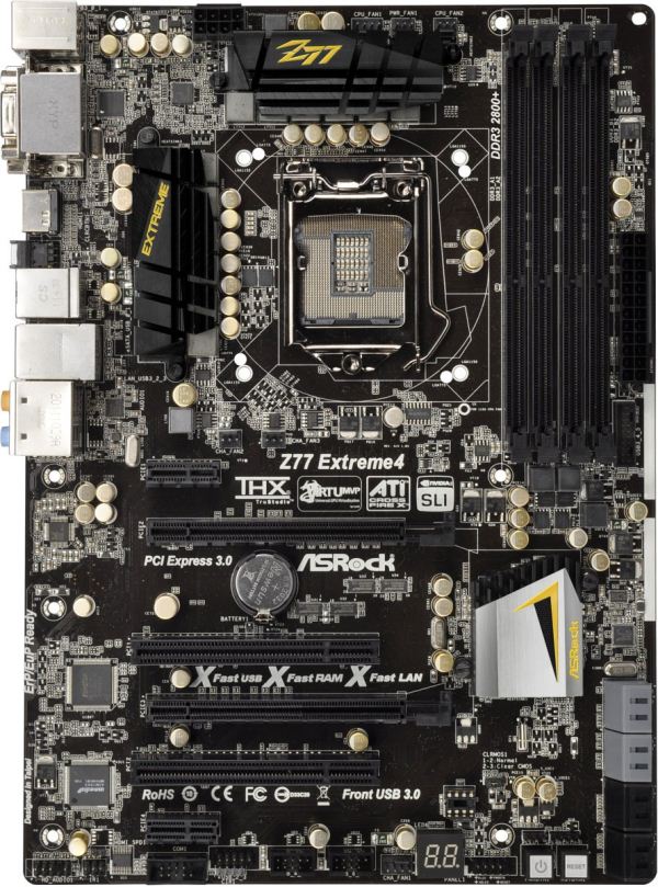
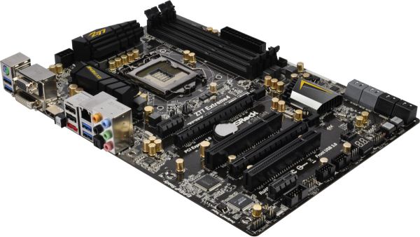
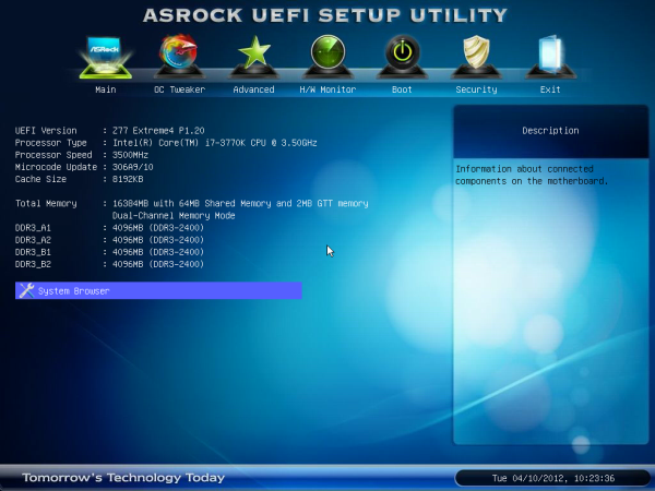
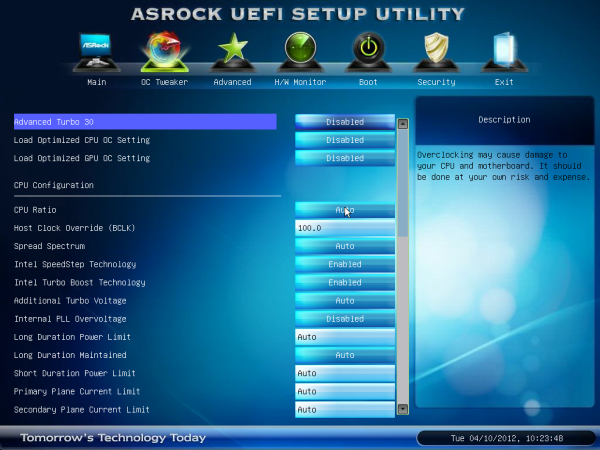
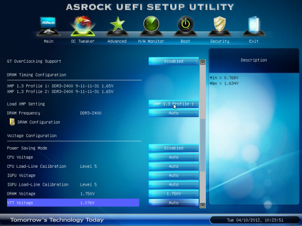
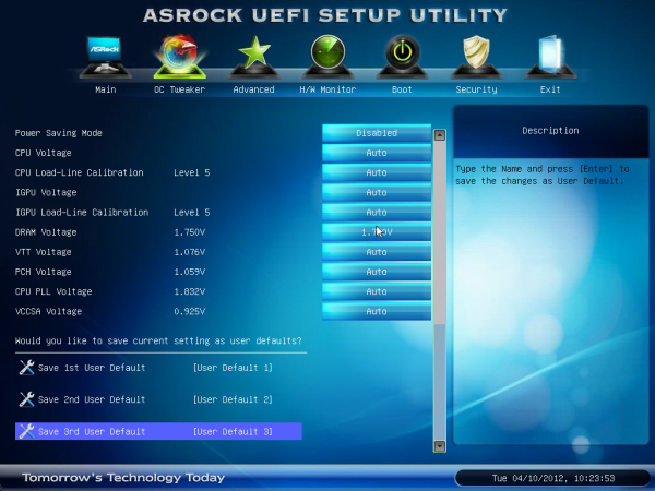
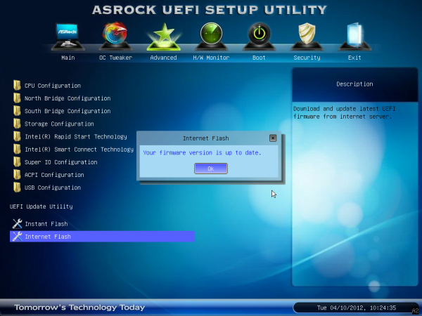


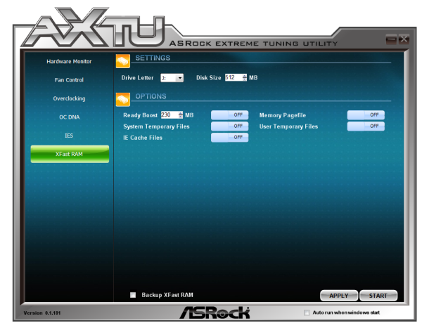


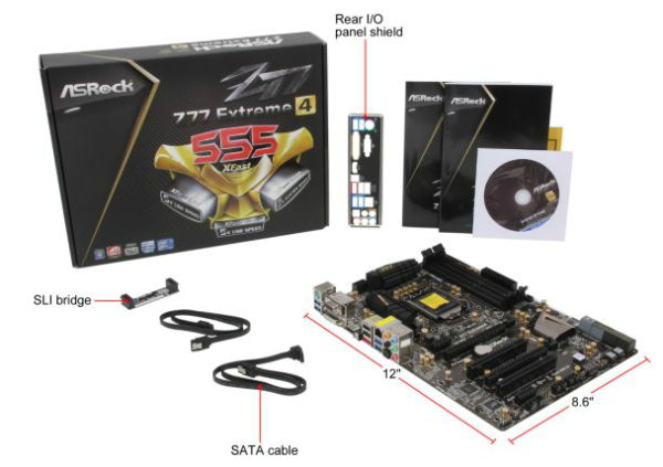
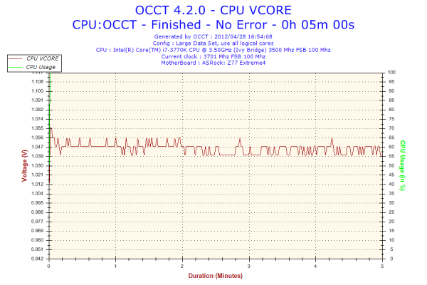
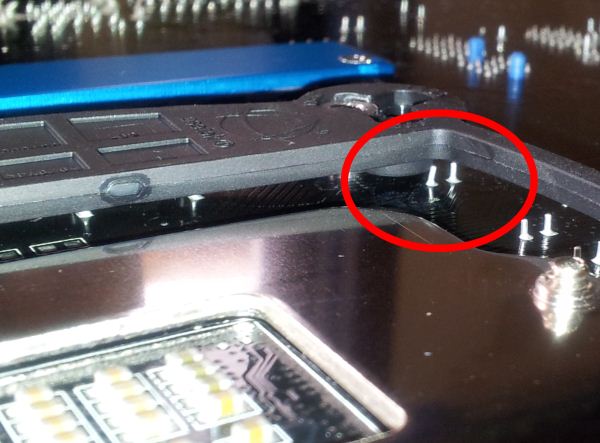
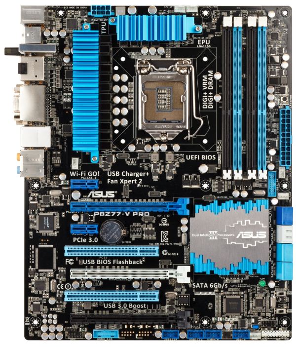
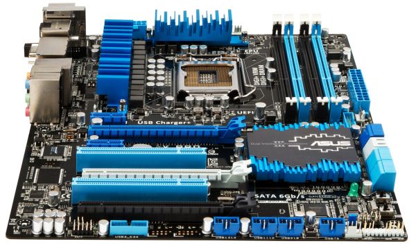
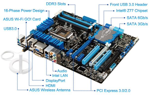

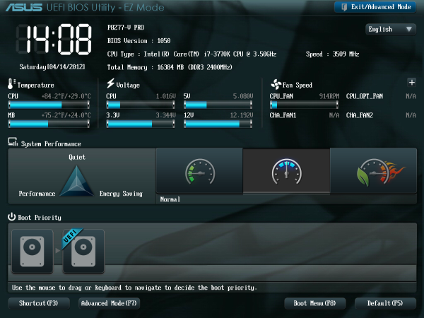
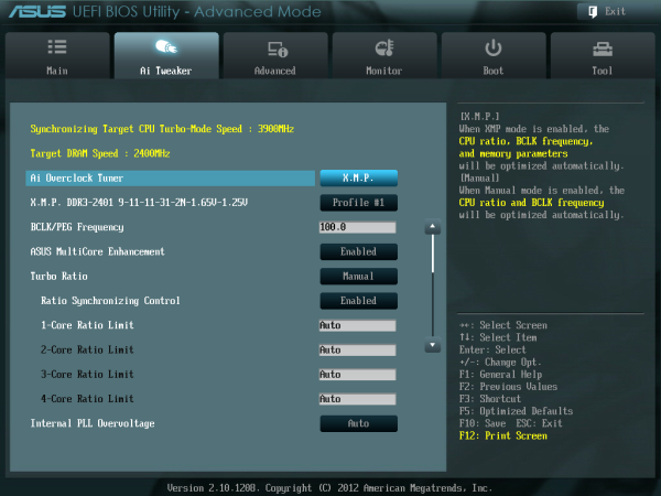
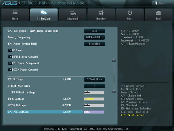
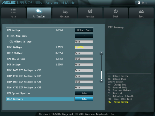
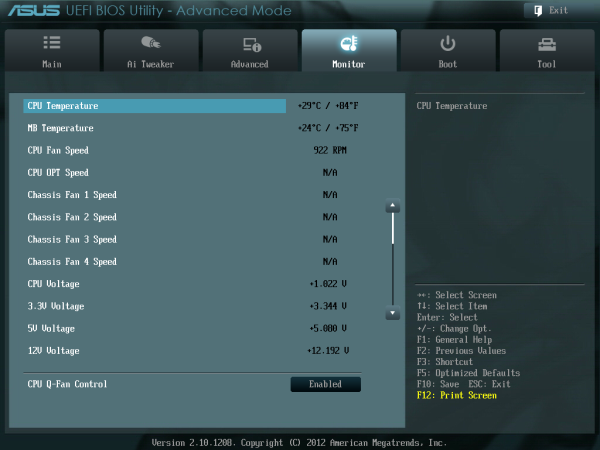


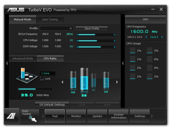
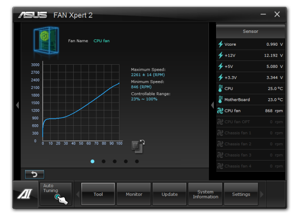
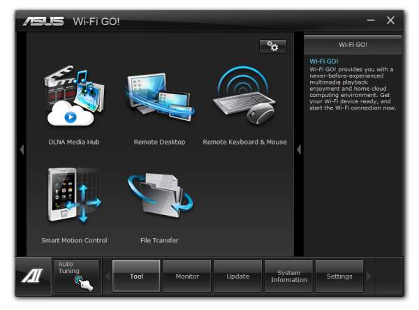
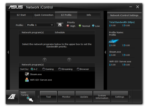
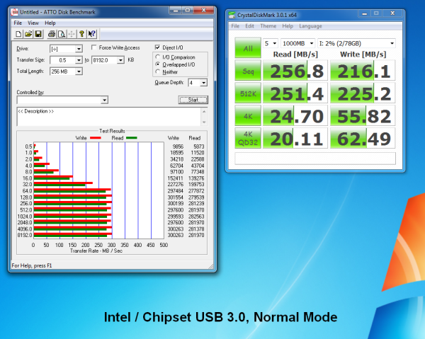
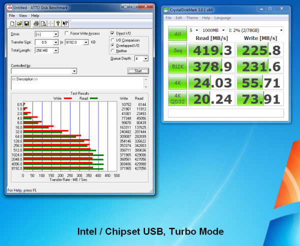
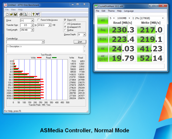
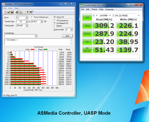
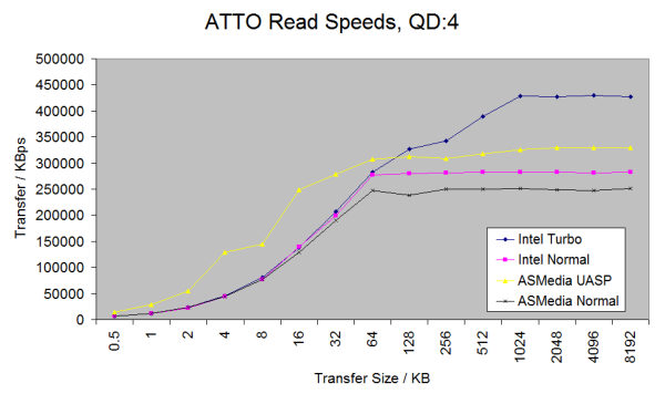
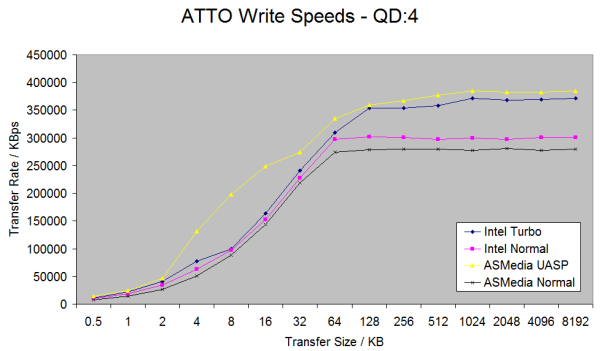


_575px.png)
-B_575px.png)
-bb_575px.png)
