The GIGABYTE MW51-HP0 Motherboard Review: Consumer Meets Workstation for Xeon W
by Gavin Bonshor on March 6, 2019 9:30 AM EST- Posted in
- Motherboards
- Intel
- Gigabyte
- Workstation
- server
- Xeon-W
- C422
- MW51-HP0
Visual Inspection
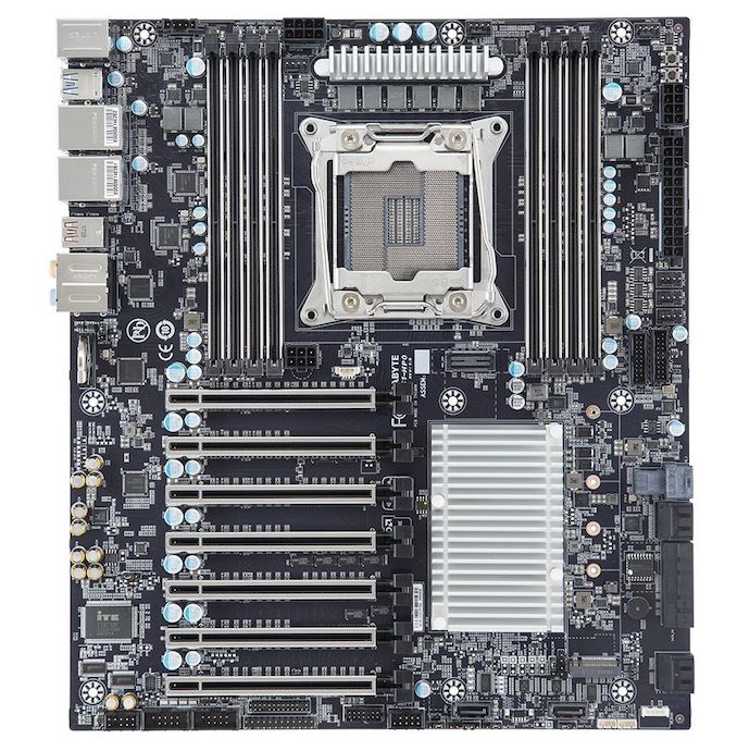
The GIGABYTE MW51-HP0 is a workstation-centric model which is designed for professional use and supports the Intel Xeon-W Skylake based range of processors. The MW51-HP0 uses the CEB form factor which means it’ll fit into an E-ATX chassis, but the location of the LGA-2066 socket is slightly different than what you'd find on a consumer-based board. The board's silver and black theme are consistent with a professional-grade board; the PCB is matte black with silver heatsinks and slot armor.
As expected from a professional-grade workstation motherboard, a lot of the focus on features is in the hardware support, and as a result the MW51-HP0 has a lot of headers and jumpers. A total of six 4-pin headers are dotted around the edge of the board; one dedicated to the CPU fan and five for chassis fans. A PBS connector is located at the top left-hand side of the board, with two of the 4-pin headers also along the top. Flanking either side of the LGA-2066 socket is four RAM slots with the board offering eight in total. The MW51-HP0 allows for memory speeds up to DDR4-2666 at 1.2 V, with both RDIMMs and LRDIMMs supported at 64GB/DIMM and 128GB/DIMM respectively. Meanwhile, underneath the CPU socket is an XDP port for debugging, which for users looking to use XDP, is available separately.
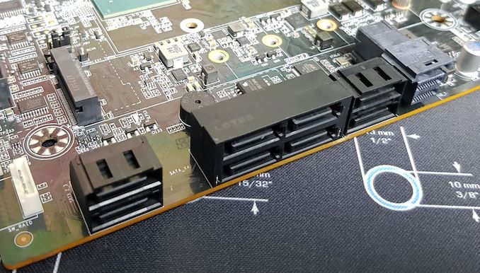
On the storage front, the MW51-HP0 offers a total of ten SATA ports, with eight deriving from the C422 chipset and the other two being controlled by a Marvel 88SE9172 SATA controller. RAID 0, 1, 5 and 10 arrays are supported between the ports. A single M.2 slot is also present, which is wired up for PCIe 3.0 x4 and can accomodate sticks up to 22110 in size. Next to the SATA ports on the right-hand side of the board we also find a single U.2 connector, offering support for Mini-SAS drives. Meanwhile at the bottom right-hand side of the board are two SATA DOM connectors, which also includes two headers. Finally, located next to these is a VROC connector.
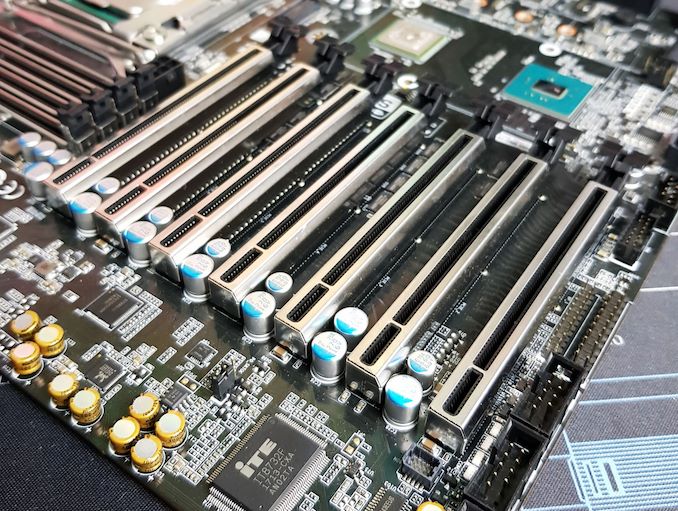
For PCIe I/O, the GIGABYTE MW51-HP0 has a total of seven full-length PCIe 3.0 slots. With so many slots, the board also uses a 6-pin PCIe 12 V power connector (located above the top slot) to provide the necessary power to all of the PCIe slots. A single Broadcom PEX8747 PLX chip is located nearby, which is cooled by the same heatsink as the C422 chipset. The PEX8747 allows the board's PCIe slots to offer a combined total of 64 PCIe lanes, which means the PLX chip is wired up to 16 CPU lanes upstream and is driving 32 lanes downstream. The top PCIe 3.0 slot on the MW51-HP0 doesn’t share lanes with any slot – so it can always do x16 – while the remaining slots do share lanes. This is depicted in the table below:
| GIGABYTE MW51-HP0 PCIe Layout | |||||||
| Number of Installed PCIe Cards on CPU |
PCIe_7 | PCIe_6 | PCIe_5 | PCIe_4 | PCIe_3 | PCIe_2 | PCIe_1 |
| x1 | x16 | - | - | - | - | - | - |
| x2 | x16 | - | x16 | - | - | - | - |
| x3 | x16 | - | x16 | - | x16 | - | - |
| x4 | x16 | - | x16 | - | x16 | - | x16 |
| x5 | x16 | - | x16 | - | x16 | x8 | x8 |
| x6 | x16 | x8 | x8 | - | x16 | x8 | x8 |
| x7 | x16 | x8 | x8 | x8 | x8 | x8 | x8 |
Due to the layout of the full-length PCIe 3.0 x16 slots, the MW51-HP0 can accommodate up to four dual-slot PCIe cards or up to seven single slot cards. Each of the slots features a metal slot reinforcer. Technically the board has four slots which operate at x16, but ignoring the top slot and its dedicated PCIe lanes, the slot below it also drops to x8. This means that the bottom six slots are sharing bandwidth in pairs of two.
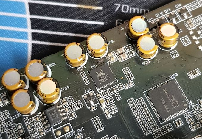
The onboard audio is provided by a Realtek ALC1150 HD audio codec and is surrounded by nine gold Japanese audio capacitors. Located just above this on the board is the BIOS battery which features a traditional jumper to reset the CMOS.
Along the bottom of the board is the majority of the MW51-HP0’s headers and switches. From left to right is a front panel HD audio header, a pair of serial port headers, a front panel header, a single HDD back plane header, a TPM connector, and a force ME update jumper. Also present is the two SATA DOM connectors, a clear supervisor password jumper, a BIOS recovery jumper and a pair of SATA SPGIO connectors. To keep things simple, GIGABYTE has included the two SATA ports which support SATA DOM within the same area and both ports feature straight-angled connectors.
In the top right-hand corner is a power switch and a reset switch, which are right next to one of the 8-pin 12 V CPU power inputs. There is a further second 8-pin 12 V CPU power input on the board as well, which is located just above the LGA-2066 socket. The board uses a 24-pin 12 V ATX power connector and just south of this are three of the chassis fan headers and two USB 3.0 headers.
Touching more on the USB capabilities of the board, the GIGABYTE MW51-HP0 has plenty of USB ports on the rear panel. All told there are two USB 3.1 G2 ports (Type-A and Type-C) and eight USB 3.1 G1 Type-A ports. Notably, the USB 3.1 G2 Type-C connector can deliver up to 3A at 5V for high drain devices and/or slightly faster charging. Meanwhile GIGABYTE has included two USB 3.1 G1 headers (four ports) and a single USB 2.0 header (two ports) to allow users room for expansion. Also located on the rear panel is a PS/2 combo port, five 3.5 mm color-coded audio jacks and an S/PDIF optical output powered by a Realtek ALC1150 HD audio codec, and two RJ45 ports each controlled by individual Intel I210-AT GbE NICs.


33 Comments
View All Comments
dipsha35a - Sunday, November 10, 2019 - link
http://www.organiccompleteproteinpowder.com/dipsha35a - Sunday, November 10, 2019 - link
BlueberriesDon’t worry; these berries won't cause an oompa-loompa-like reaction. In fact, they're nutritional superstars, filled with fiber, vitamin C, and cancer-fighting compounds. And studies suggest blueberries may even improve memory !
http://purathriveliposomalturmericextractreviews.c...
dipsha35a - Sunday, November 10, 2019 - link
http://organifiredjuicepowderreviews.com/